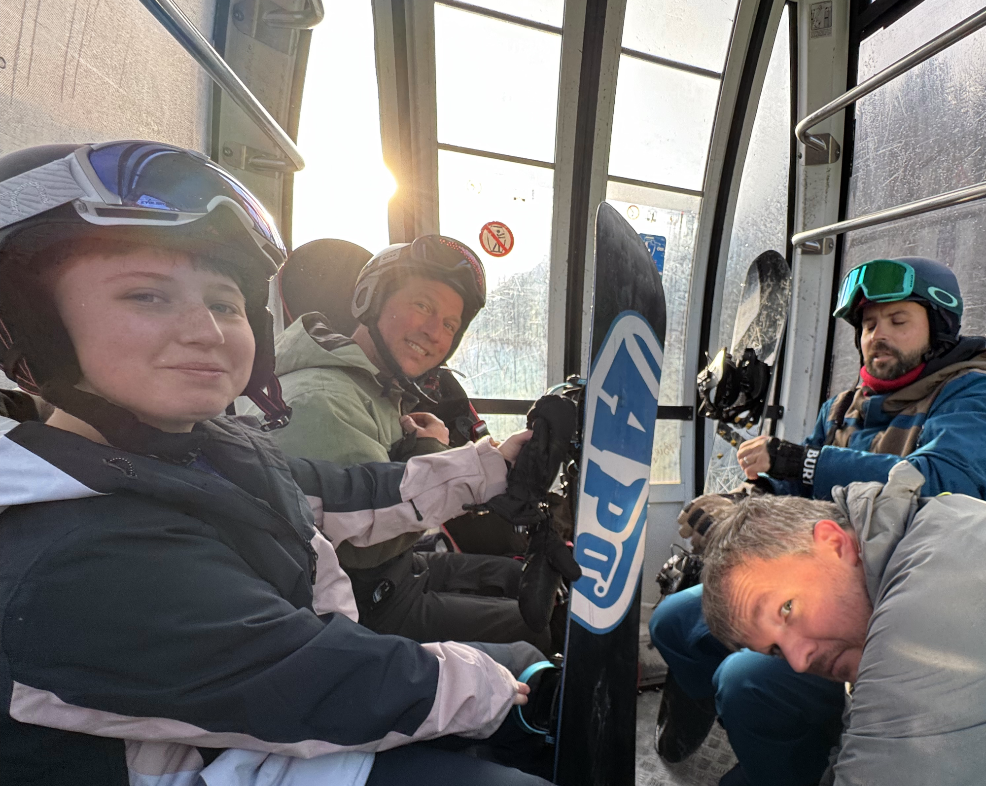
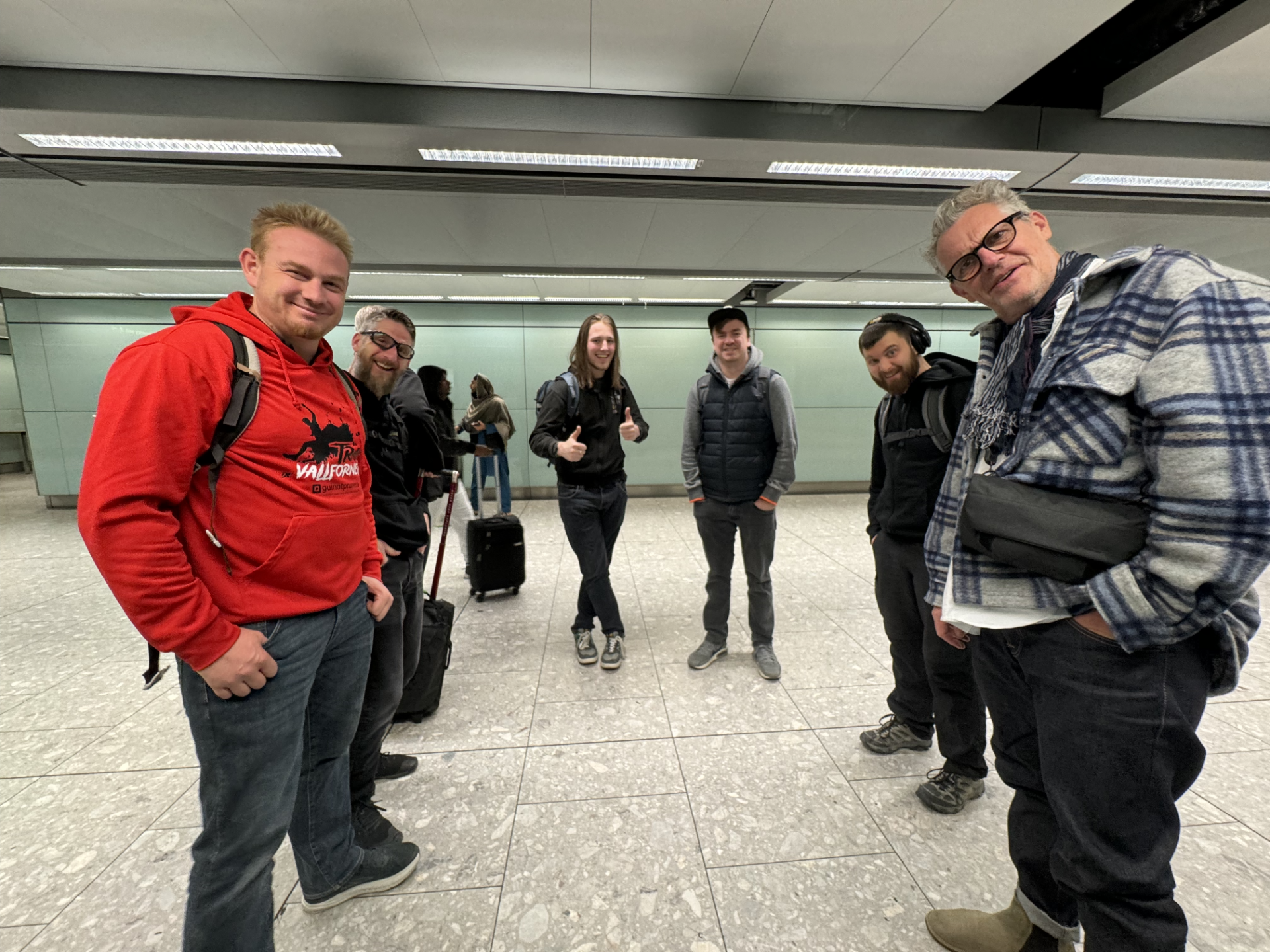
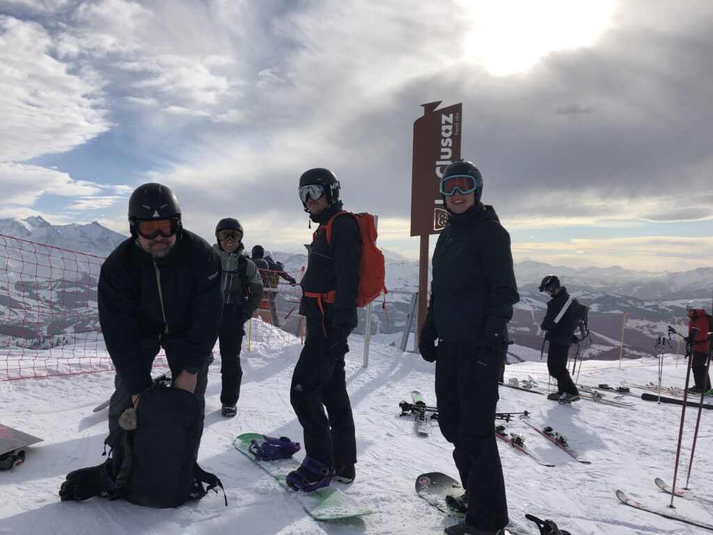
Its almost June already, the first half of 2024 has flown over so quickly so heres a quick recap of whats been going on so far. After the joy awards 2024 I had a week or so at home and then it was time for the yearly snowboarding trip. There was 8 of us going out his year to La Clusaz, James, Charlie and myself form the UK, Ruben and Fernando from Spain and finally Matt Pillerin and their 1 year old Tilda from Estonia.
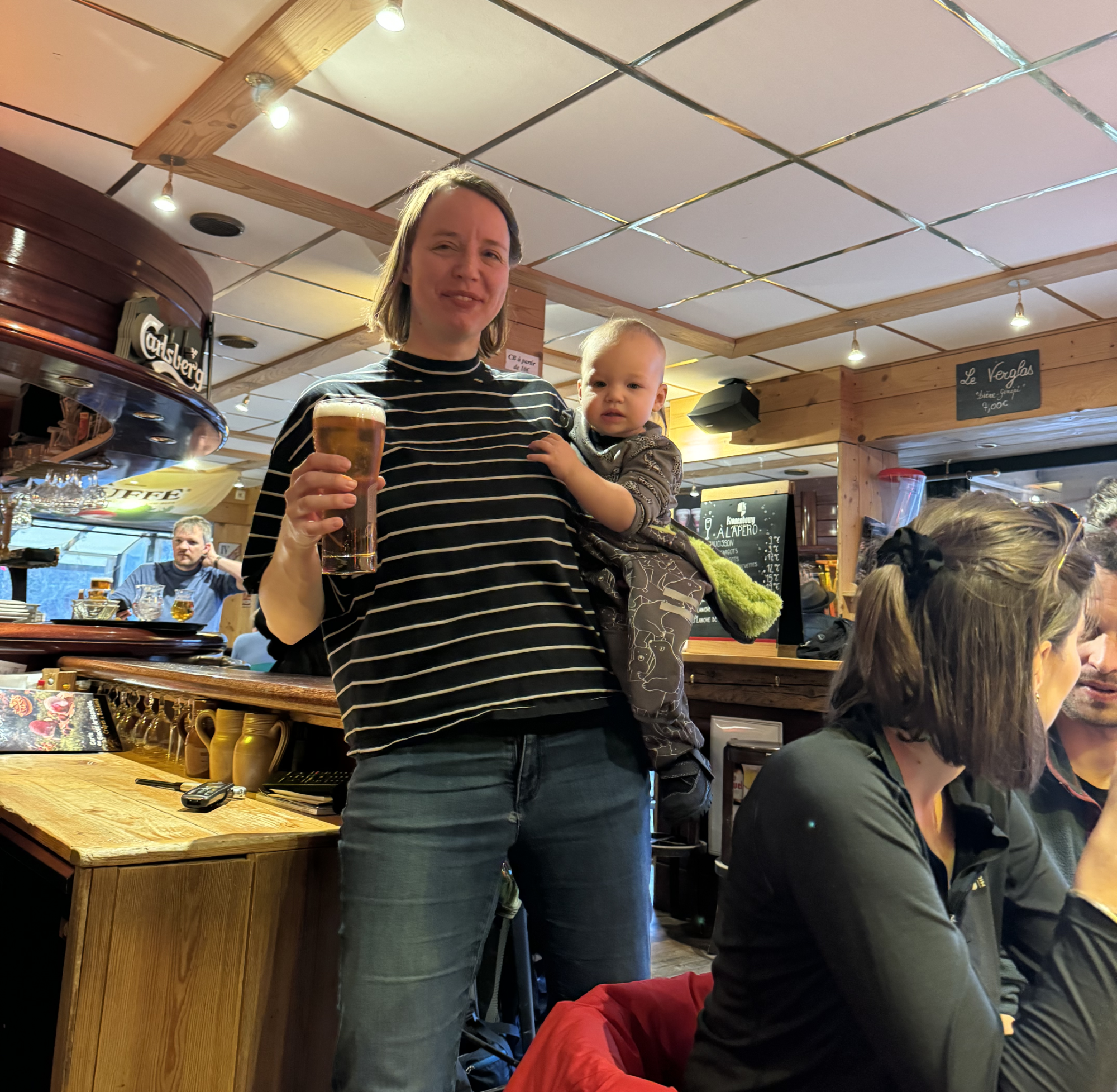
We all met in La Clusaz to be greeted by some incredibly hot weather and immediately thinking that the snow wasn’t going to last very long at this rate. Luckly up on the slopes it was still cold enough and we all spent a great week on the slopes during the day and eating drinking and playing board games on the evening.
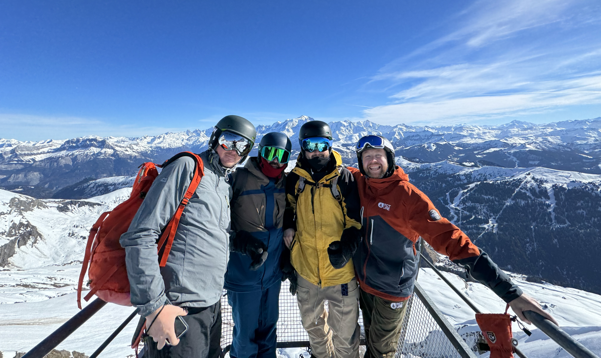
We managed to get sa few black runs in this year without any injury and this is Matt, Ruben, Fernando & Myself at Massif de Balme where despite the heat in the town we always had plenty of snow on the top of the mountain. As always it was a great week in La Cluzas well spent with friends.
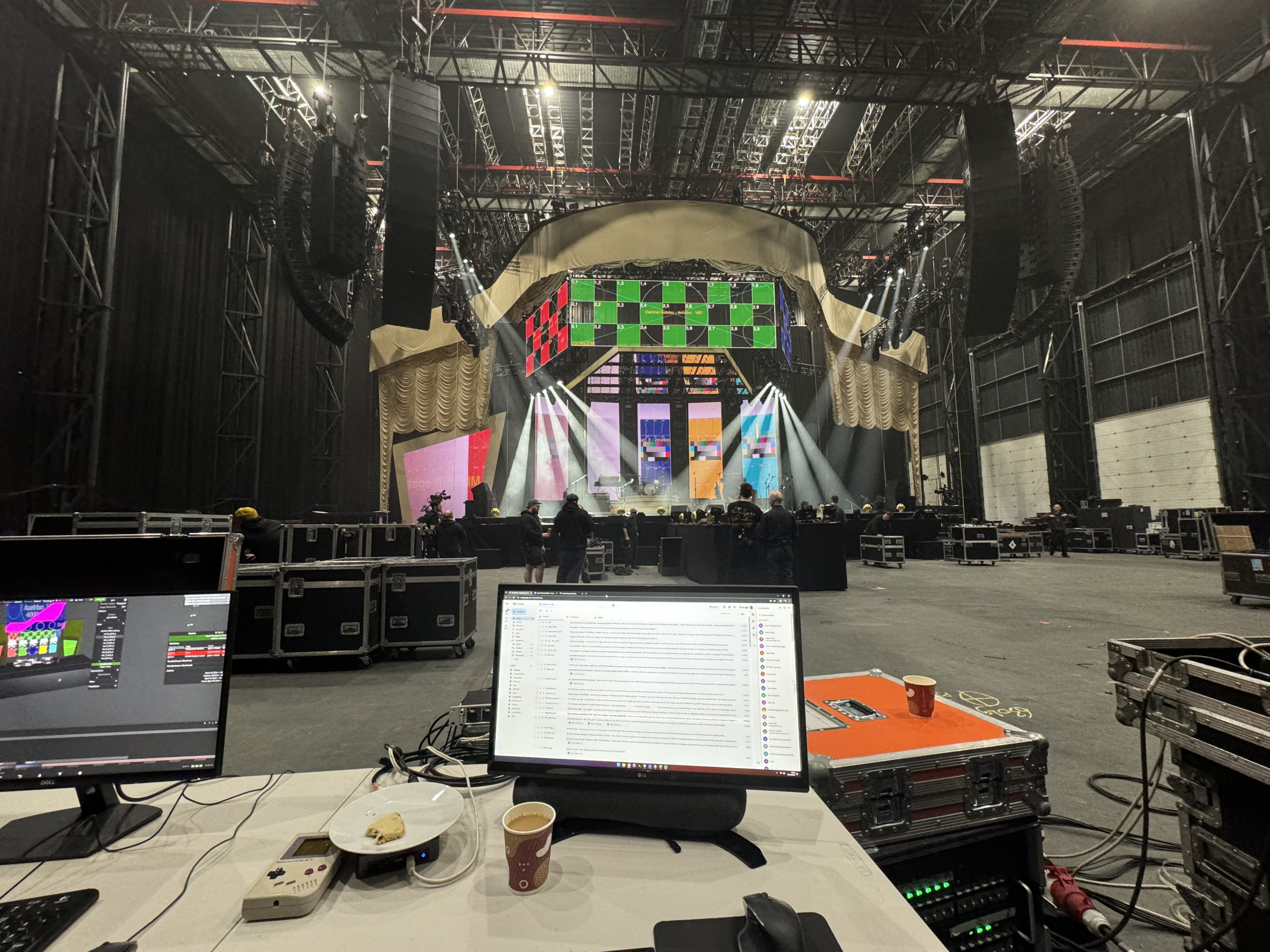
Straight after snowboarding I was headed to ProductionPark at Wakefield to help Pete Tilling program the 2024 Niall Horan tour. We had Caspar and Jos from SHOP doing content who I believe we had met on email, on another job and nice to finally meet in person.
I’d done some pre production for the moving Austrian screen and the general project setup but onsite there was some quite heavy lighting integration where we were sending lots of video to DMX from table screens in d3, mainly the light box above the stage and we tried sending to some of the movers upstage but that part was cut as it just didn’t work.
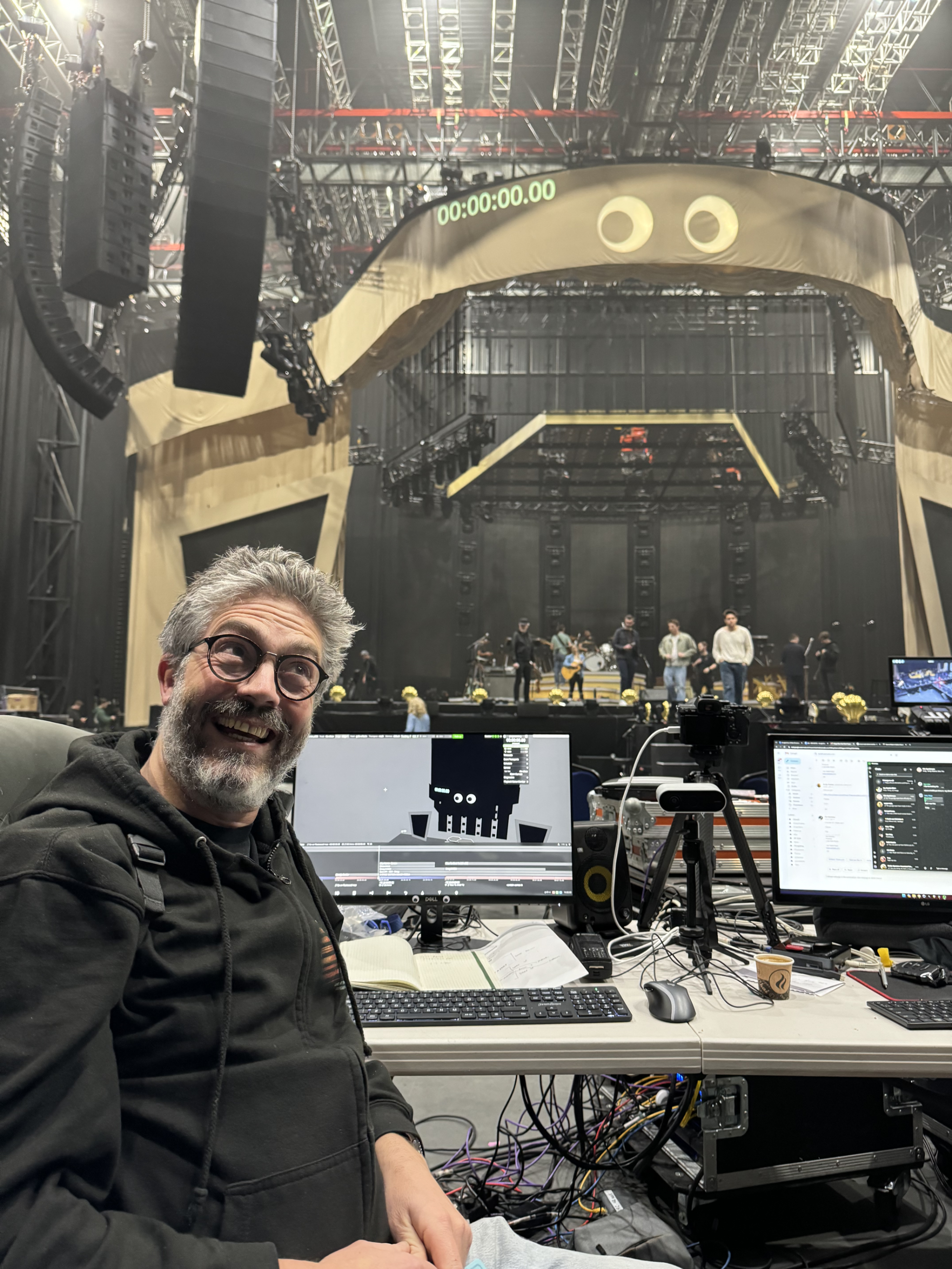
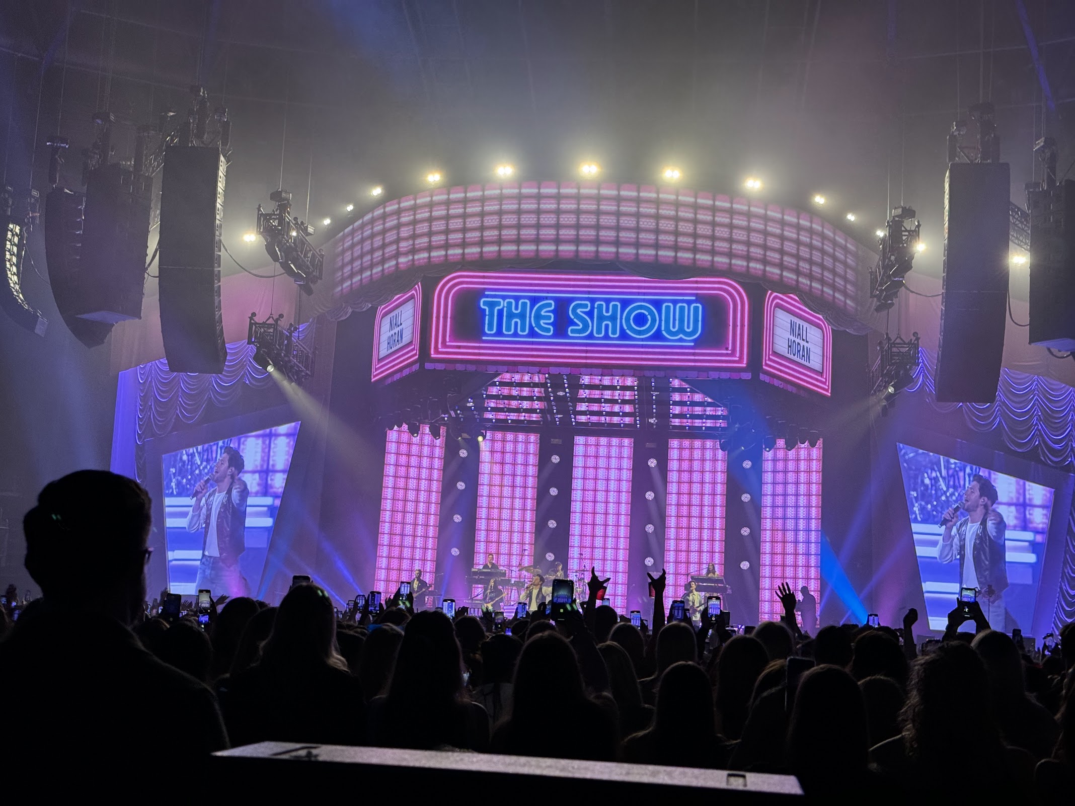
For over a year now each time I’m programming a show and in rehersals mode I put some animated googly eyes up which I made in January 2023 on one of the Joy awards and they have became a staple programming asset since then. During Niall programming the eyes were up on the border between rehearsing songs, as we got closer to final rehearsals Ben, the creative director told us he, and Niall would like to keep the googly eyes in the show.
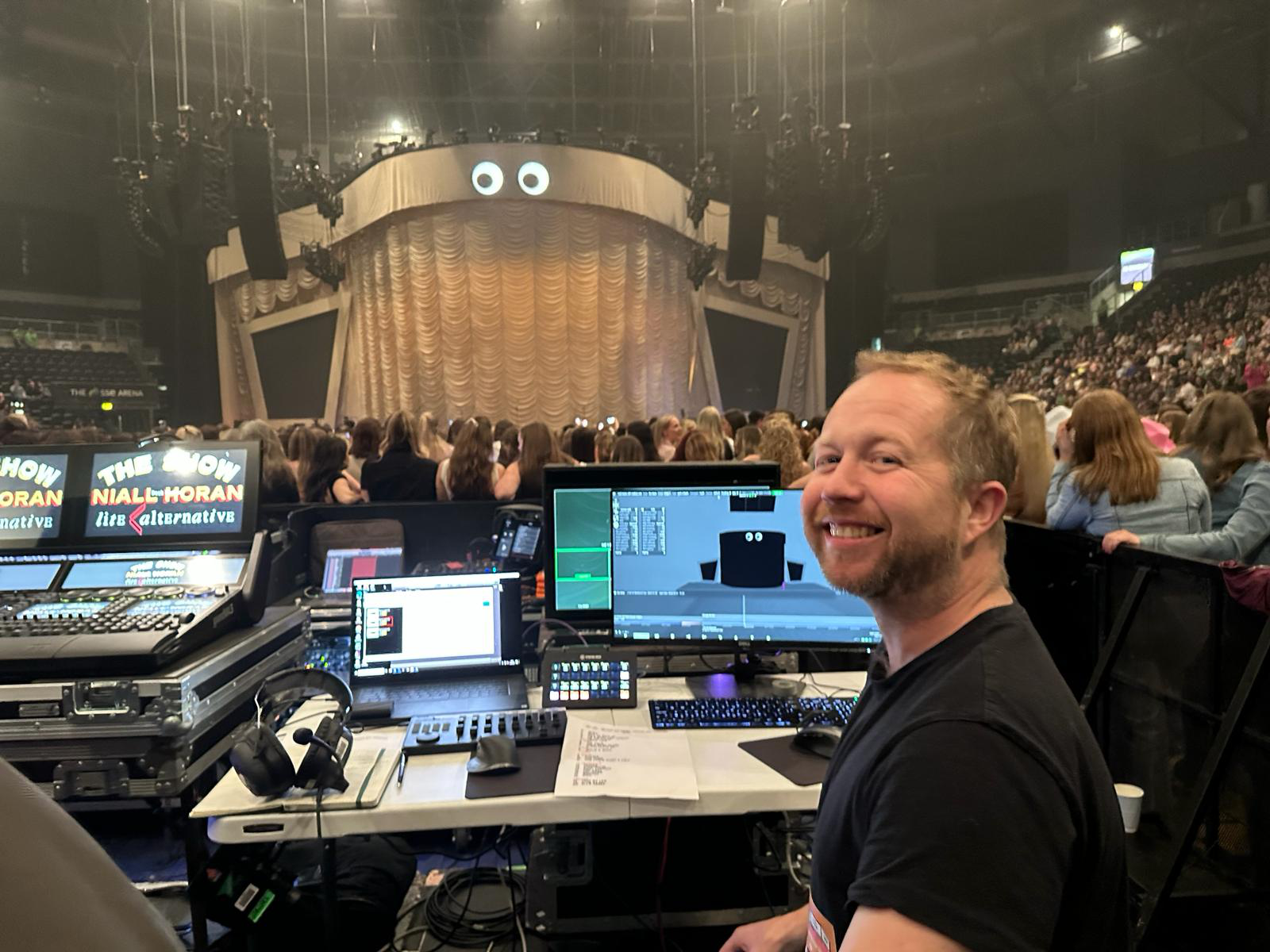
I found it so funny and quite pleased that they wanted to keep the eyes which come up on the last song just before the band come on, and below is me at the first show in Belfast late Feb 2024.
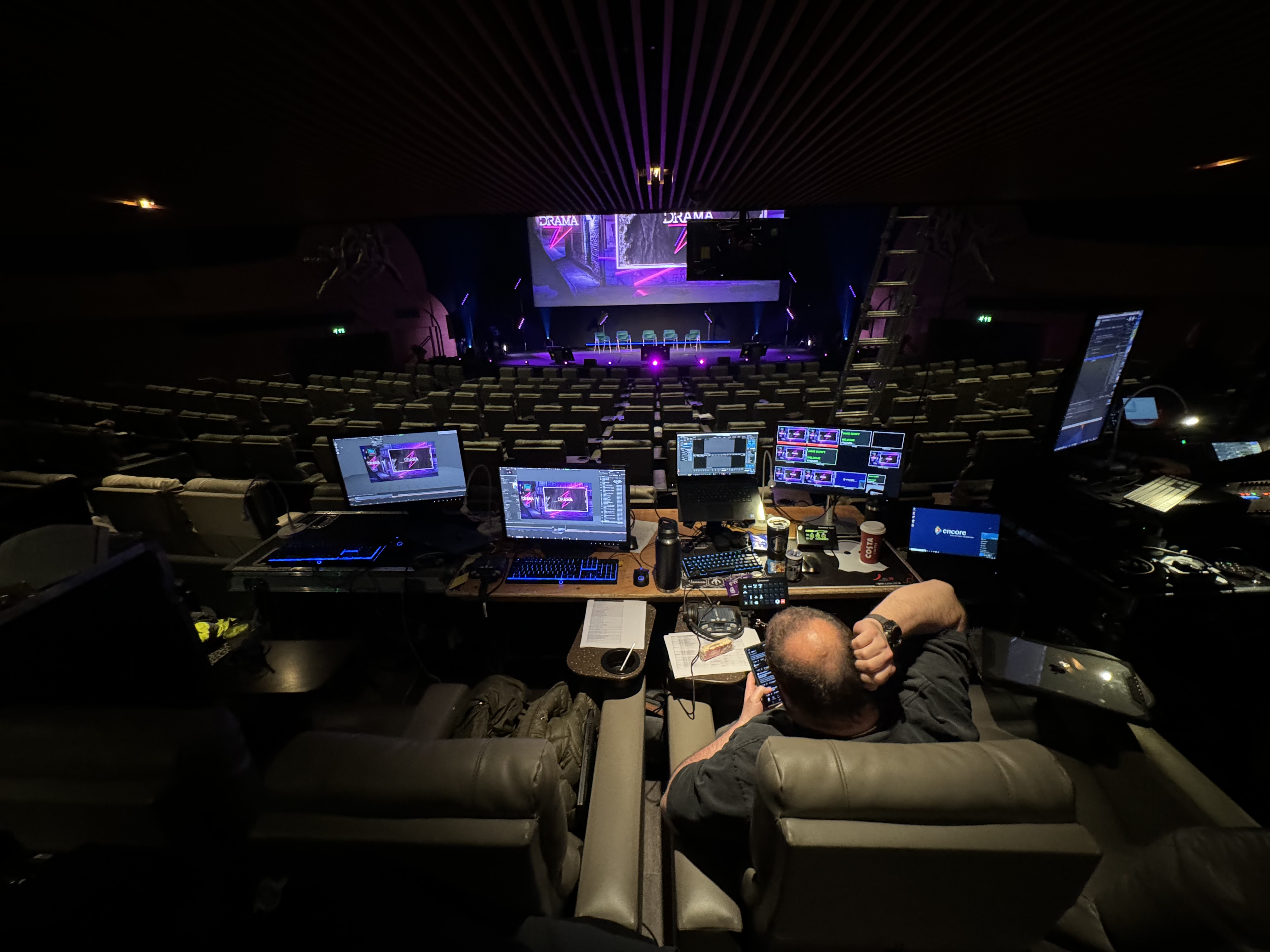
Shortly after returning from Belfast I was down London with Graymatter for a ITV showcase/premier thing at Leicester Square Odeon cinema. It was nice to see Dan from Graymatter and also Dave & Toby from Hawthorn who I didn’t know were going to be there.
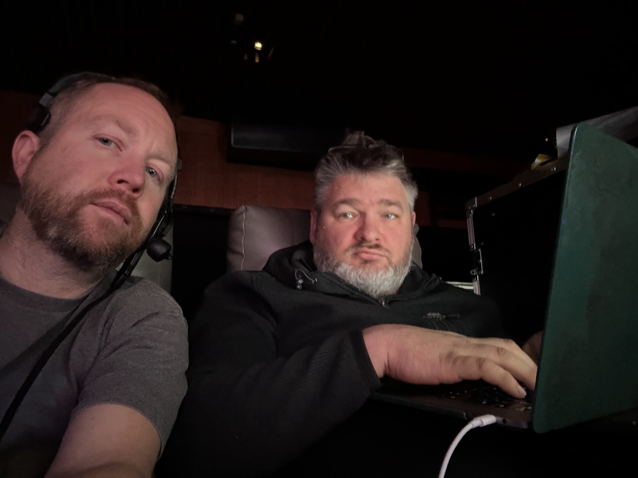
The operating position was at the very back row of seats in the cinema and was pretty cosy, “Smile for the camera Dan!’
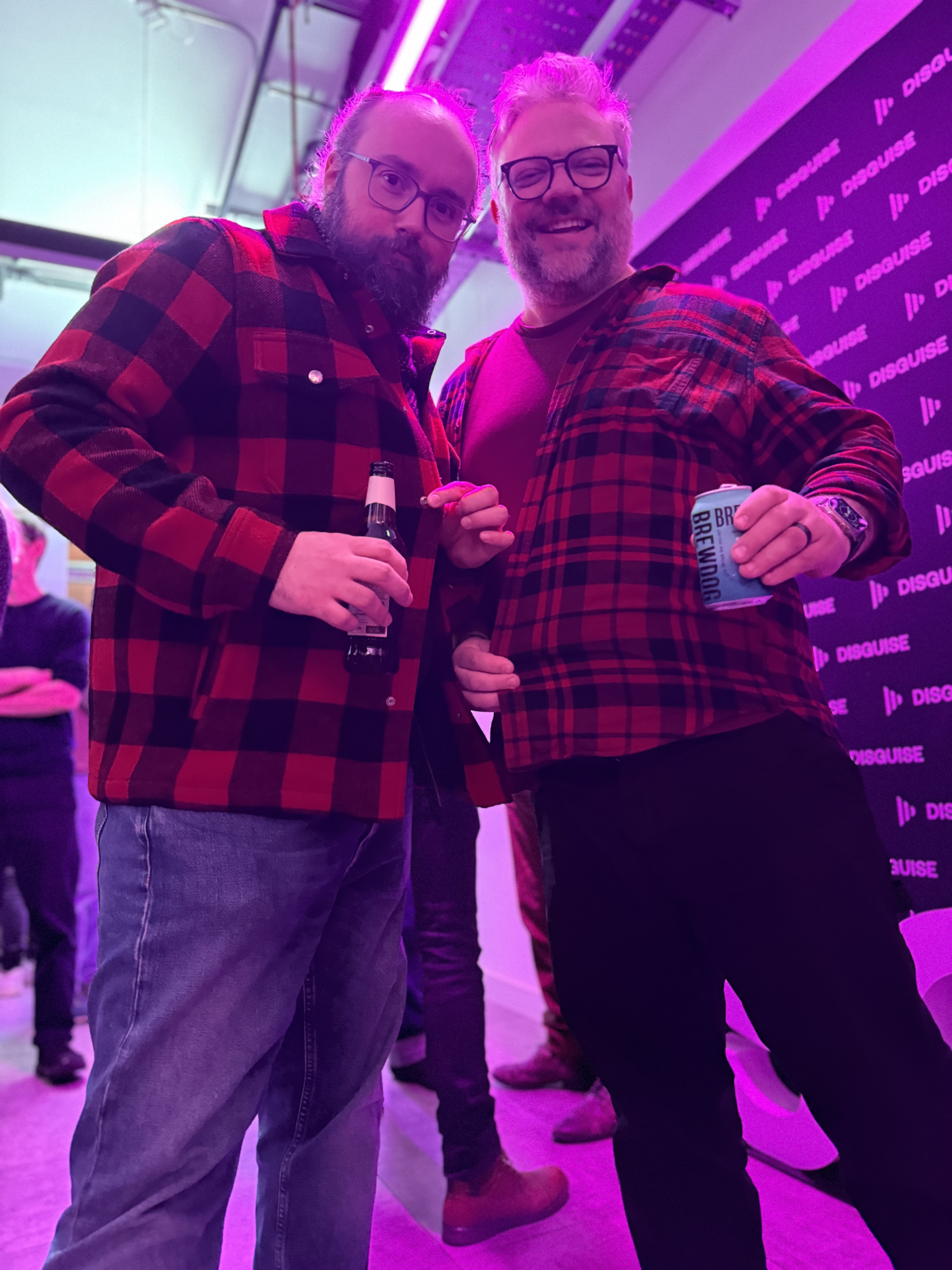
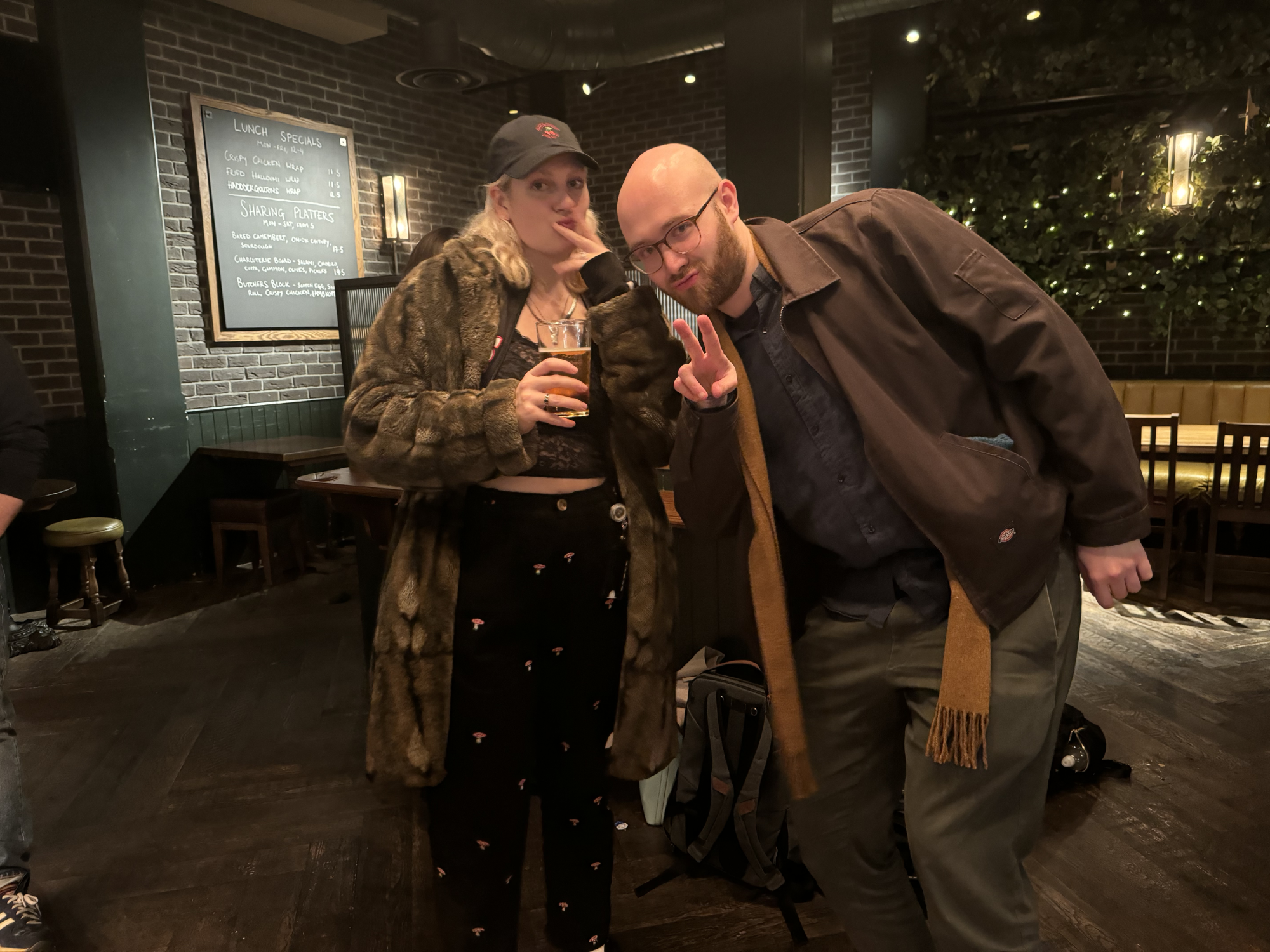
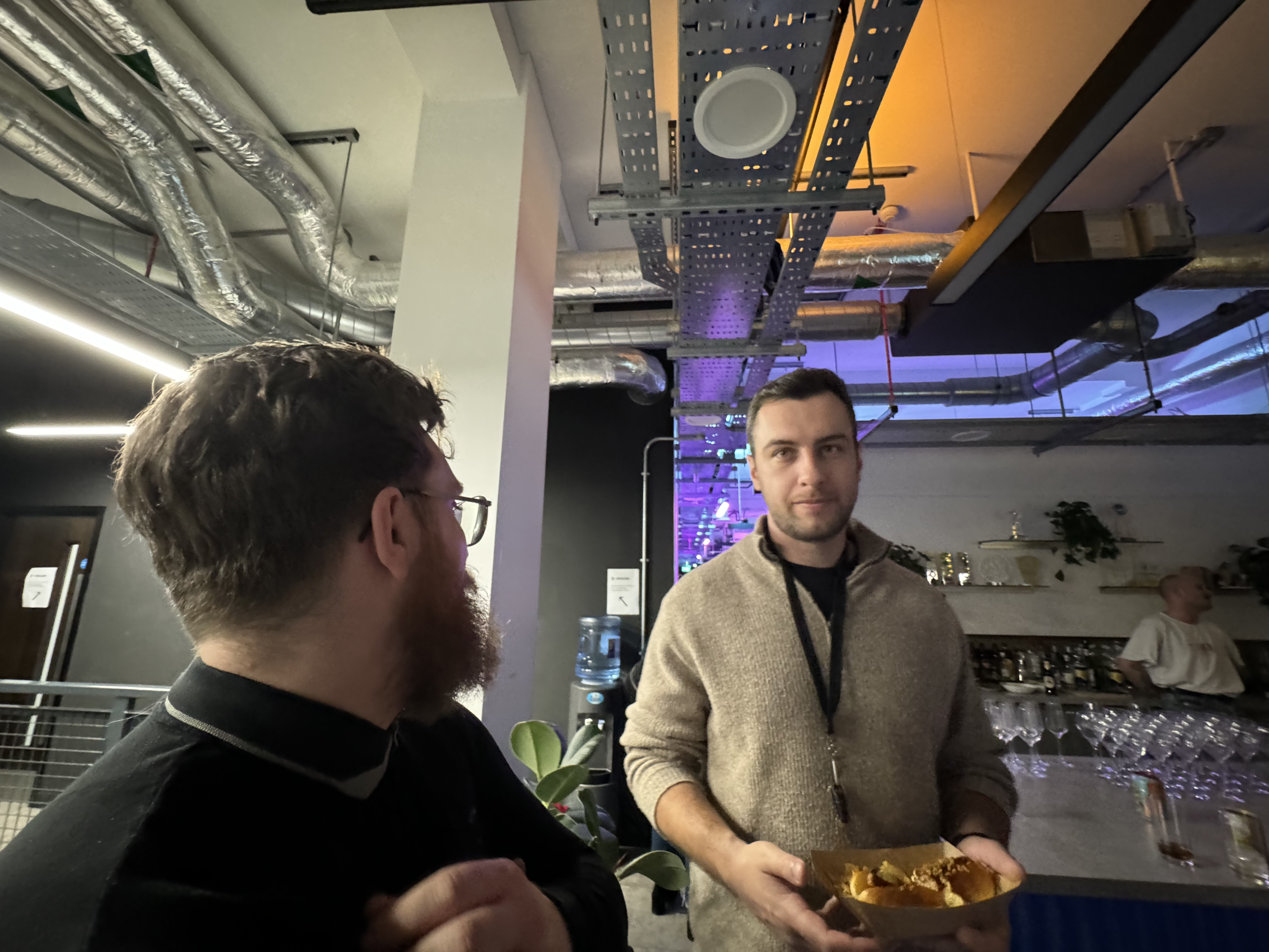
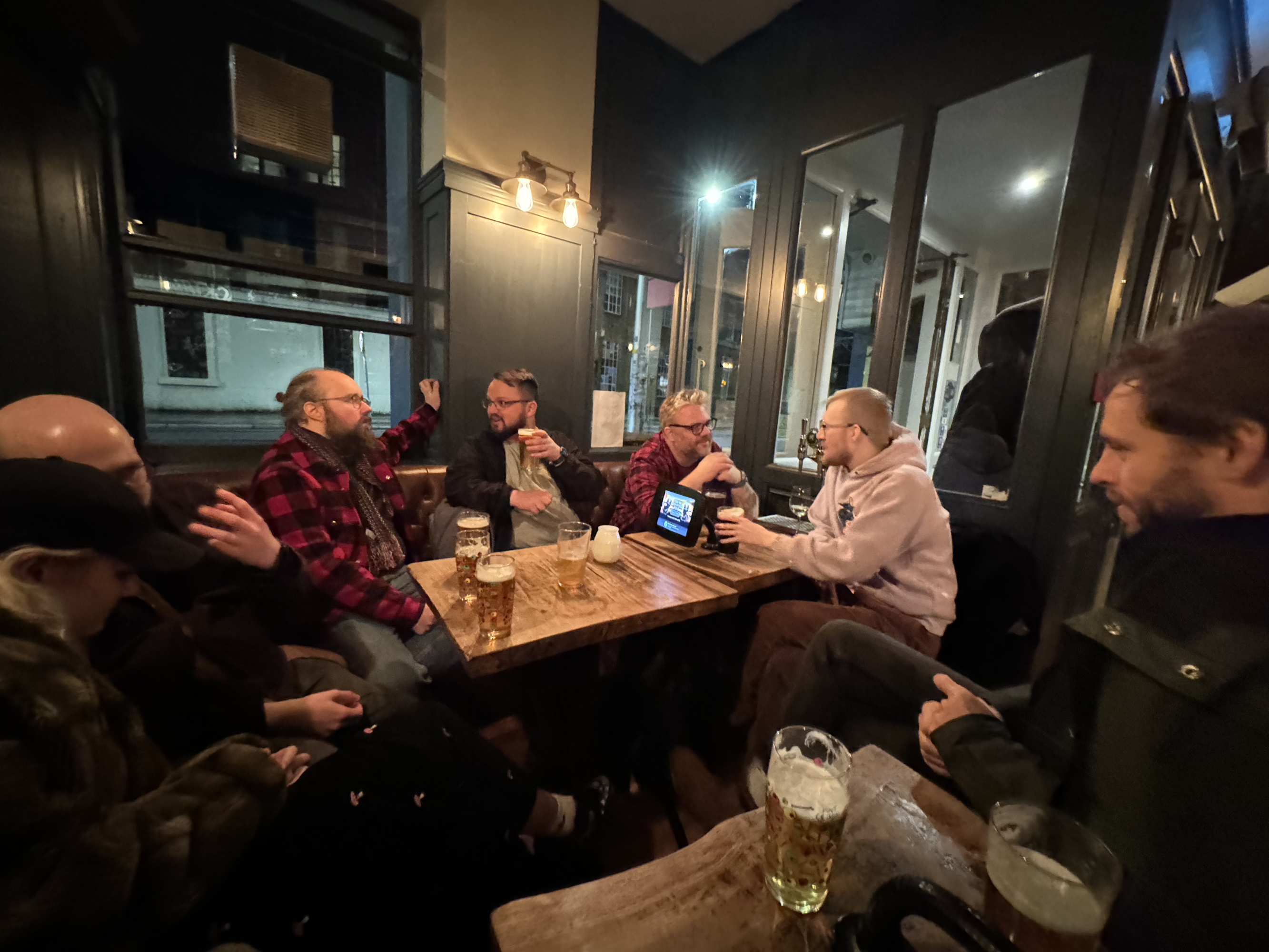
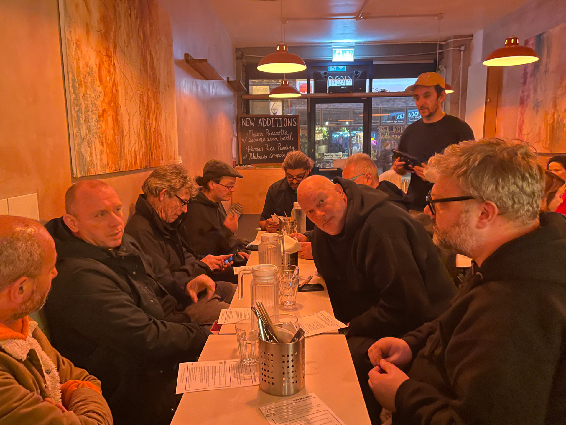
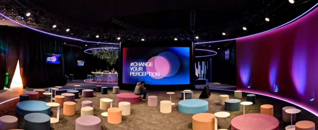
Another fun thing which happened in February was the d3 “after dark” event aimed to help the company reconnect with the user community. It was great to meet old friends and put faces to names of new friends. The gathering started at d3 hq at southwark and then we splintered off to a few pubs. After the event it was even more unclear which direction the company disguise is heading but everyone had a good time chatting shit and trying to figure it out.
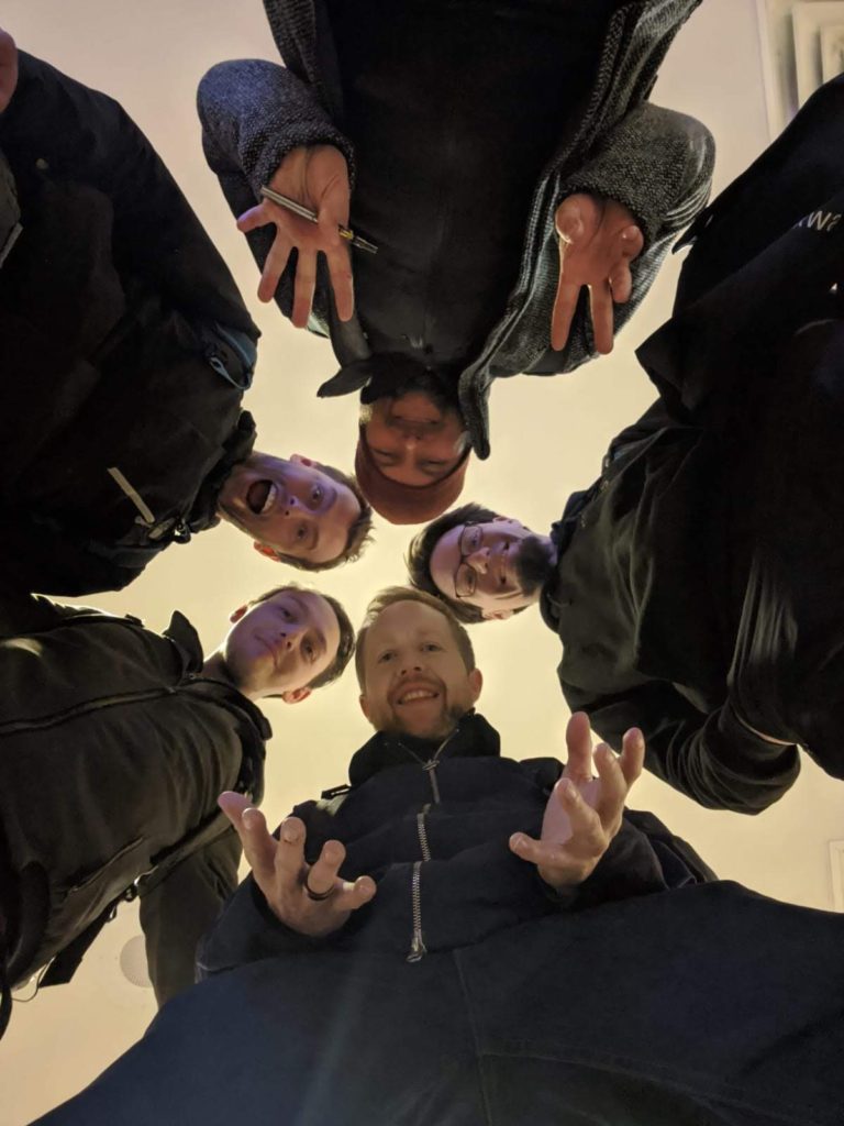
Last pub of the evening with these lovely people.
There’s has been many other things and jobs that have happened this year but unfortunately for the blog, so many projects are under NDA these days so can’t write about this at the moment. After the d3 get together my next job was with the lovely people at Pixway with Paul & Ron in Amsterdam. This was a big dealer conference presenting the new line up from BMW for next 18 month. The whole event was very locked down and we all had to deposit our phones in a locker prior to going into the venue for work. this made communication quite difficult too as very few people were given radio coms. I was programming the evening show and I definitely got the easy end of the job as Paul & Ron had to deal with late content which is never fun.
It was a great week and lovely to catch up with Paul & Ron, at one point Ron and myself had both brought a couple of packets of troop waffles to work and we did collectively and up eating them all before the end of the day. I think that’s enough of an update so far, it’s kinda unbelievable that we are halfway through 2024 already and it feels like its just begun. here’s to a just as enjoyable second half to the year.
Here we are the third month into 2024 and it feels like this weeks have passed by so quickly, I was going to start updating this in January but as so often these I’m not so sure where the time has gone so here we are at March 15th.
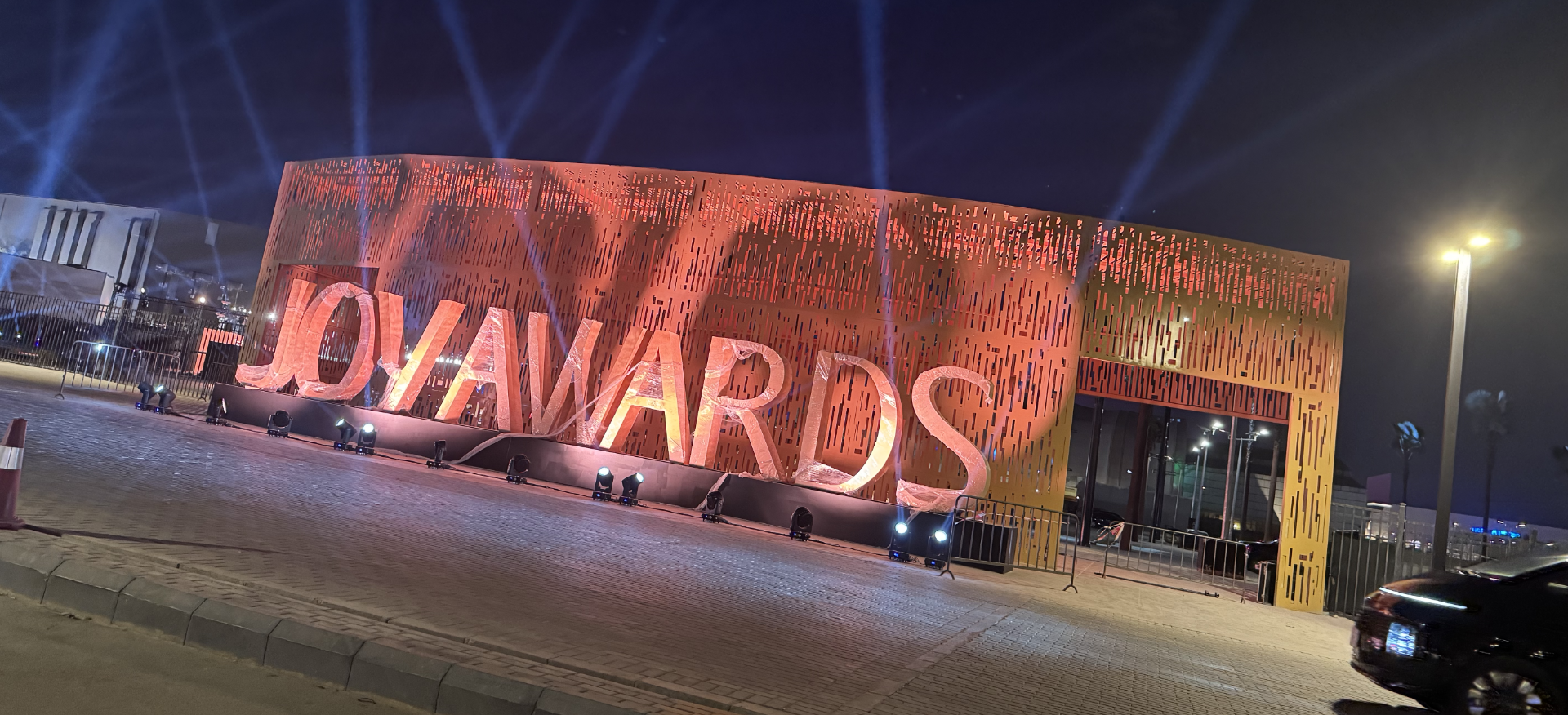
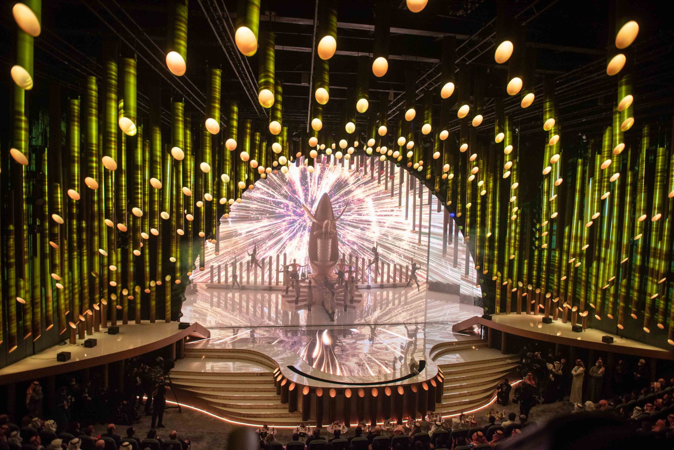
For the past 2 years I’ve assisted OgleHog/Chris Saunders with a big event in the middle east called the Joy Awards which is basically the middle east’s Film and TV awards show hosted in Riyadh.
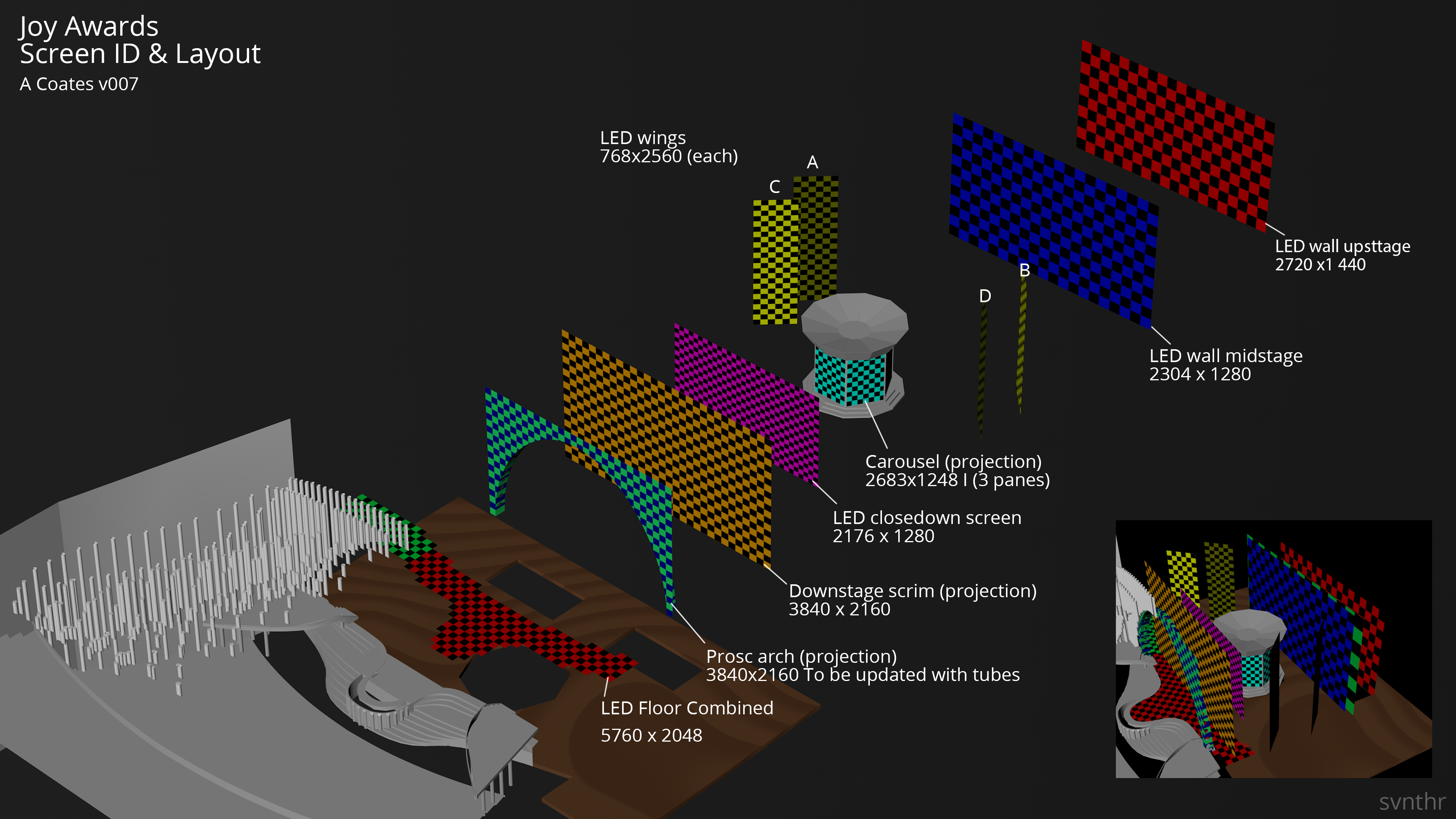
Below is a breakdown of the first one we did back in 2022, produced by Done and Dusted with set design by Stufish
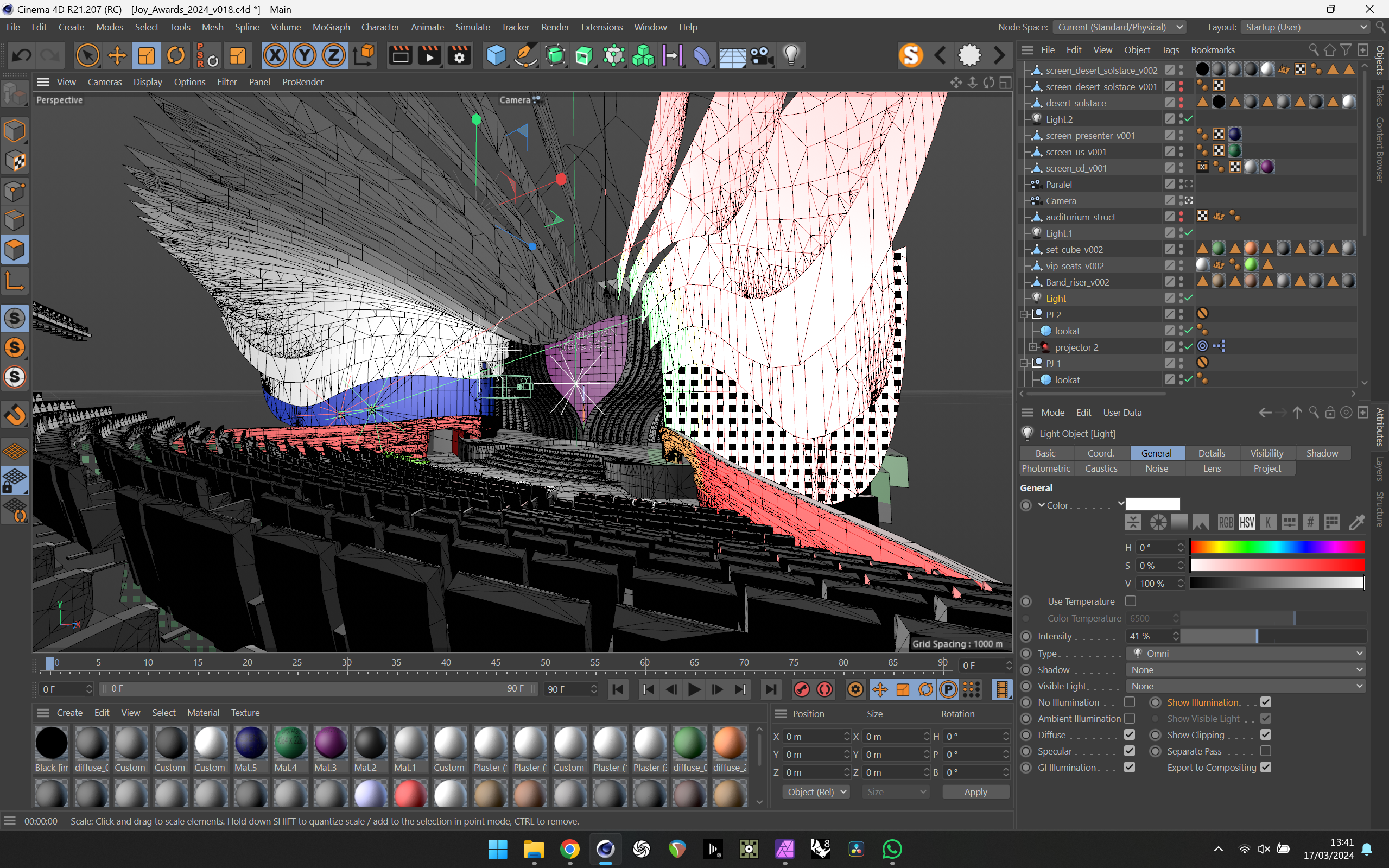
Stage screens breakdown in c4d
Tubes projection analysing with my c4d projector plugin
Tech’ing onsite
Its evolved in the past 3 years since January 2022 where we were a team of 4 of us, Dan Gray, Toby Vogel myself and supported by Creative Technology’s Carlos Aguilar. That first show was a bit “wild west” there was so much going on with many led surfaces and also projection, there was so may cues to program and the show running order and content was changing constantly. We all worked hard for our money on that gig, it was great teamwork and we pulled of a totally clean show.
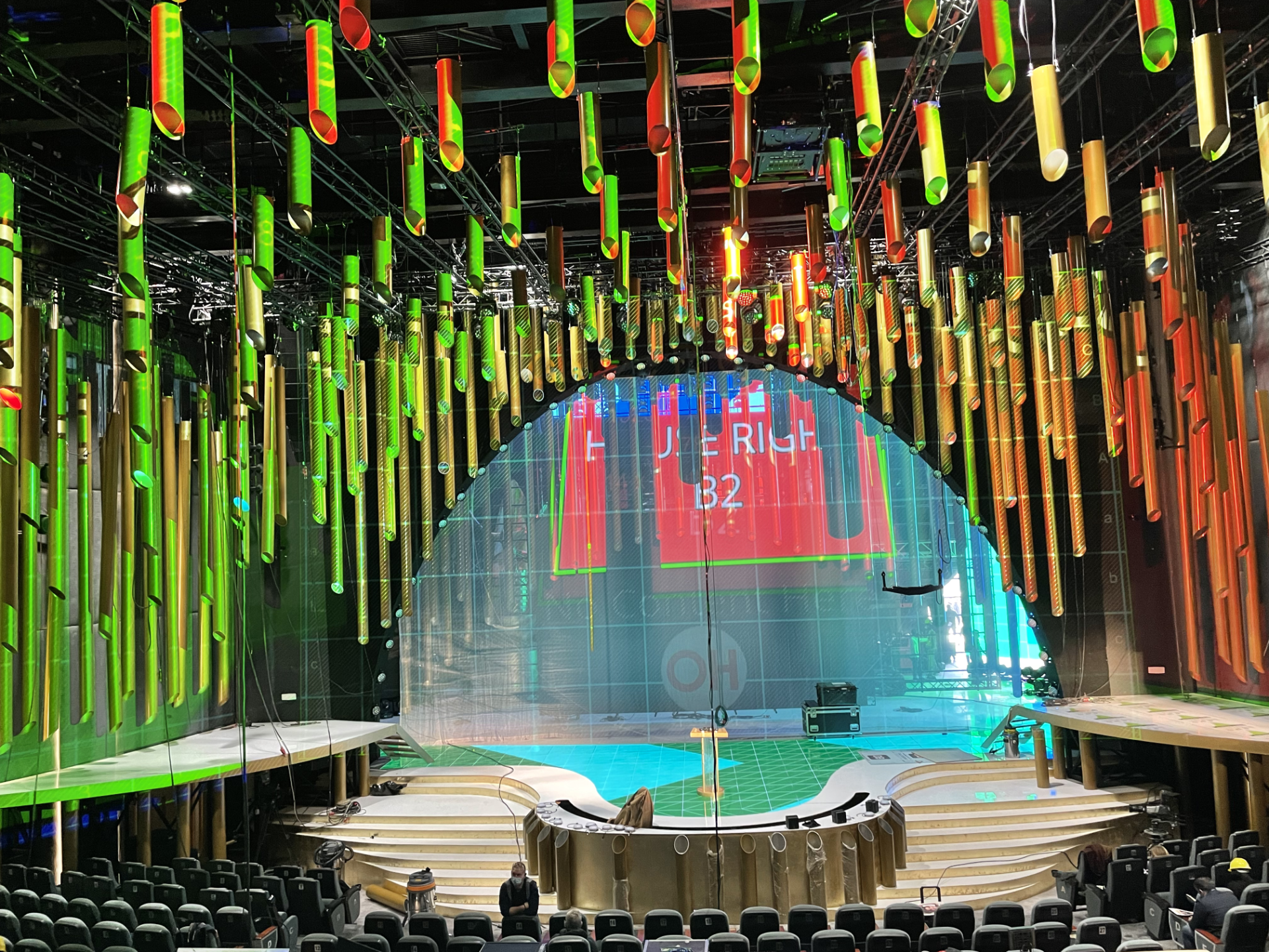
2022 show opening shot with projection on gauze & tubes plus loads of led
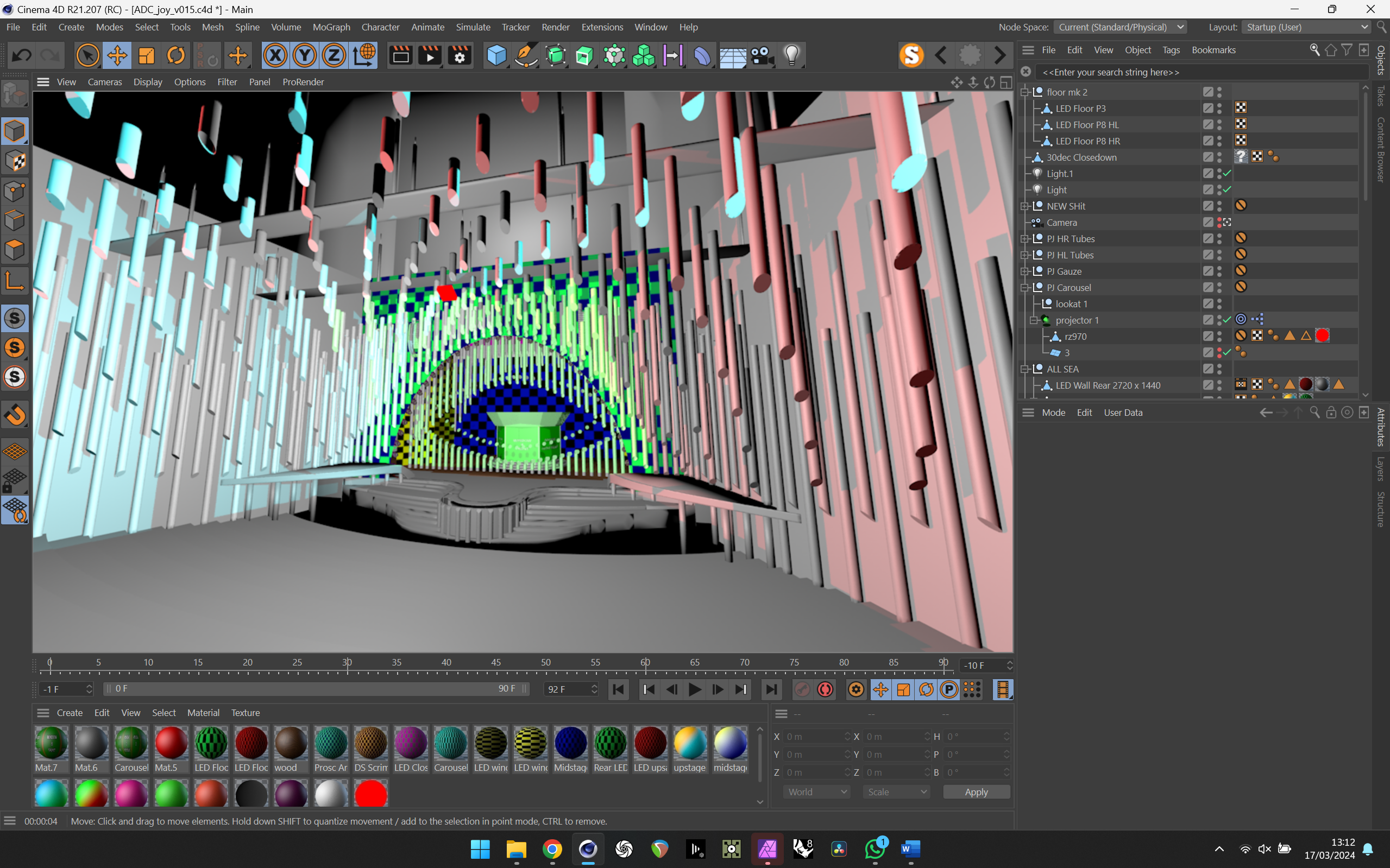
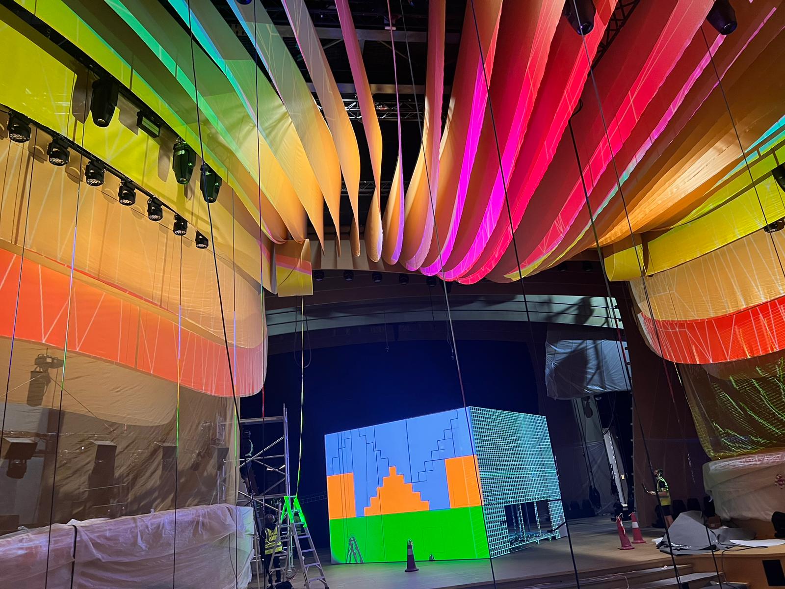
Fast forward to November 2023 and Chris called to see if I was up for doing it again and begin the video programming planning stages. There were much fewer LED surfaces this time but exponentially more projection gags with projection for almost every act and basically wherever else it could be squeezed in. Below is a screengrab from my cinema working, showing the extent of the set which was beign built to augment the auditorium.
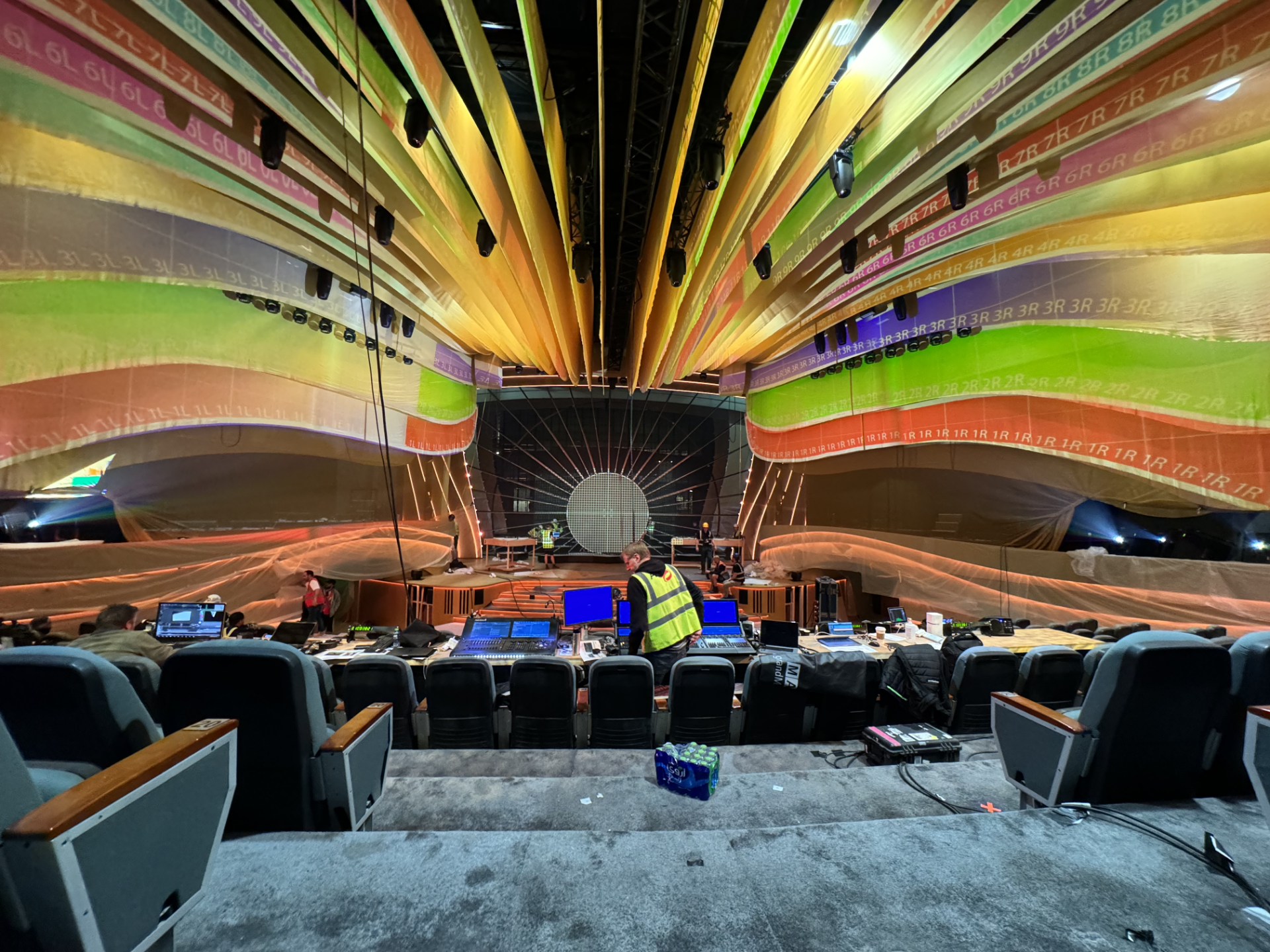
Thus years design incorporated more auditorium dressing than previous years which all was to be projected on. Over the next few weeks based on the Rhino3d from Stufish I came up with a projection design for the auditorium with some great input form Dan as he was ultimately lining this thing up onsite.
Mapping Matter early projection study
The other projection elements were very much influx with in the whole run up so prior to the equipment shipping date we decided to spec a few more projectors than we needed and some extra lens options. This meant we had enough kit to make stuff work on the constantly changing landscape of the Joy Awards 2024. Doing something like this in the UK would be much more straight forward as if you were short of kit, then its relatively easy to get extra kit sent to the gig, this is totally not the case in Riyadh at the moment.
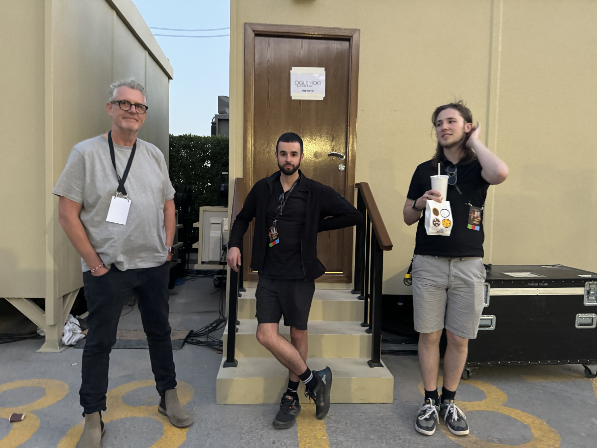
Chris Harry & Ben pondering the days events
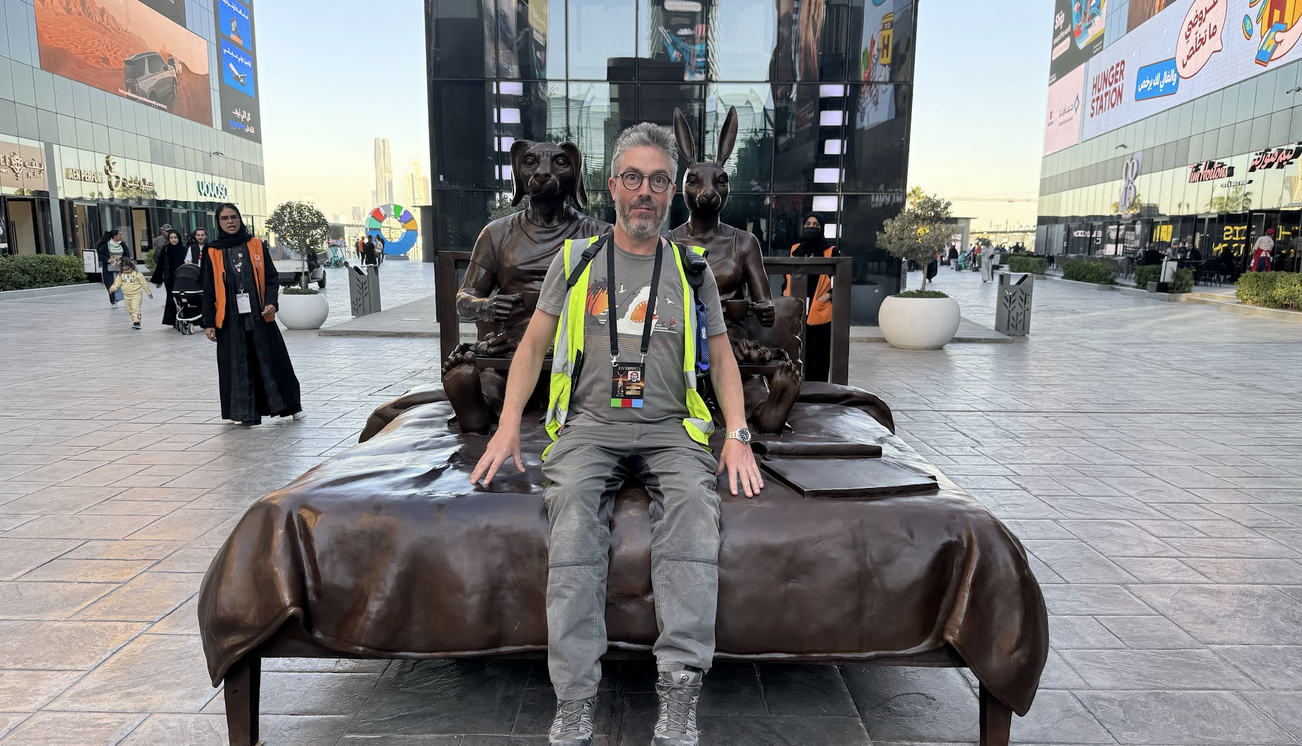
On the 7th January a team of us flew out to Riyadh for the setup at Riyadh BLVD (Boulevard) which is a bit of a cross between a theme park and a shopping mall, its pretty much the only theatre space I know in Riyadh. Pete Tilling was out a few days earlier to receive the kit and get the projectors the basic locations and was nice to see his smiling face when we arrived.
Just before getting told off for siting on the sculpture
The following few days went really quickly with the guys from QED getting the signal in, rigging and pointing the projectors. Dan and Harry did a lovely job of the server cabin which was a super tidy install. In there programming cabin there was 4 of us on the buttons, Dan Gray, Ed Joynson, Adam Power and myself. Ed and Dan eventually ended up on the late shift lining up the projection in that lovely time of evening when there is no-one else there.
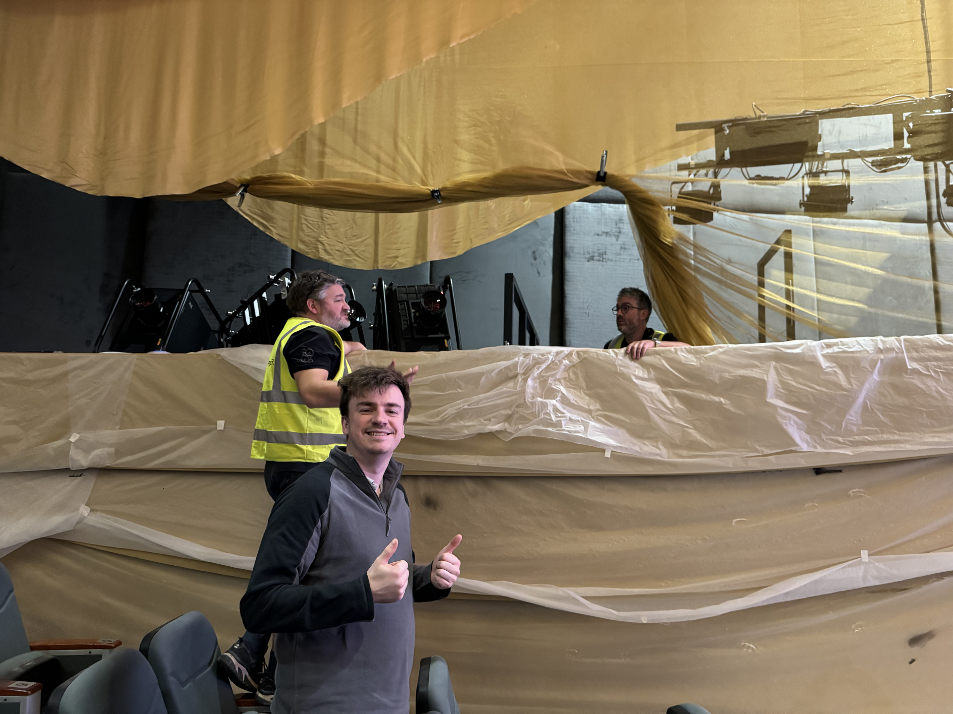
The “fins” being installed
Dan Ed & Pete
Dan lining up and sorting blends
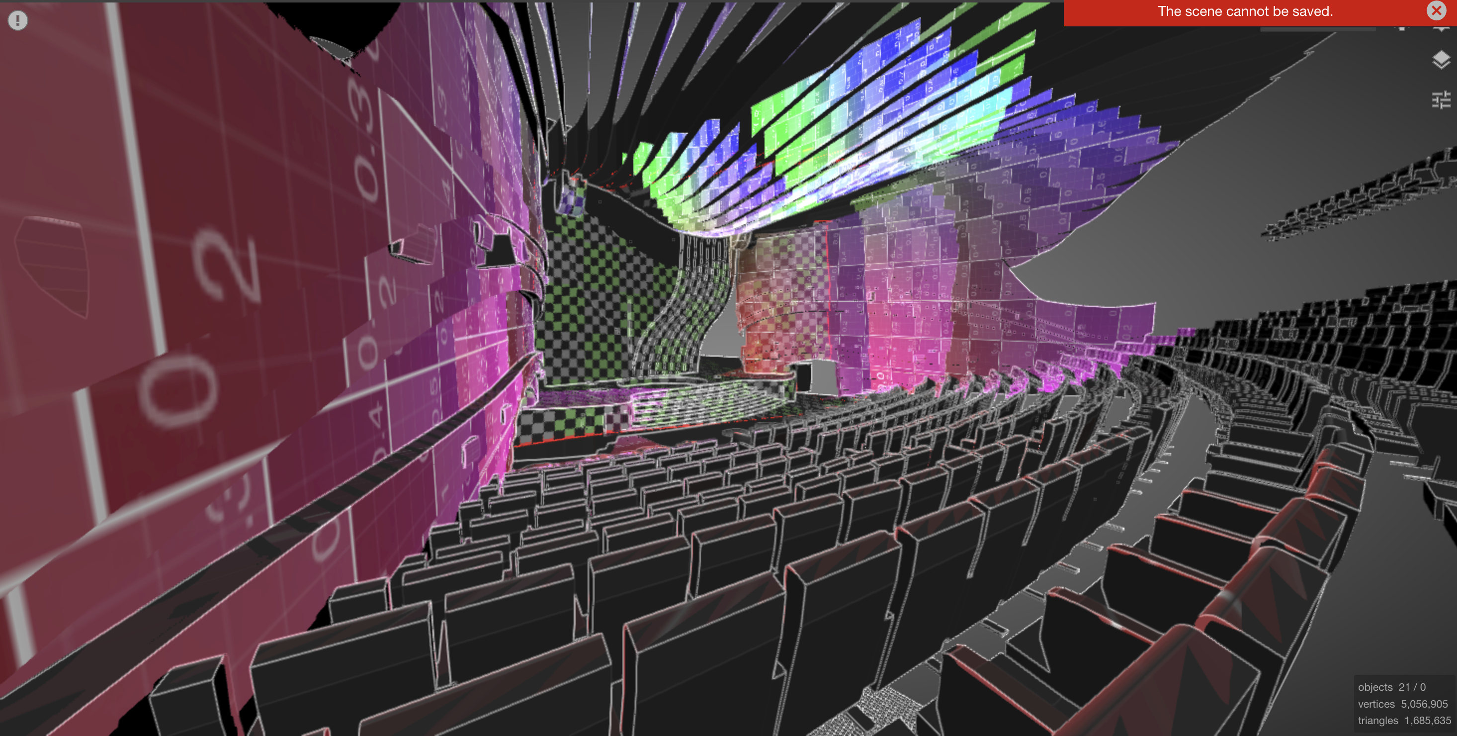
This year, I brought my laser scanner out after a bit of trouble last year where the physical set was vastly different from the 3d design, which meant Dan spent a lot of time moving 3d elements and warping in d3 to make it fit. So first thing this year once the auditorium set resting was in and complete, Dan took the Faro s70 and scanned it to create an as built point cloud, and then use that to modify the existing model to the real world setup.
With the advantage of the scan data we managed to get the map the roof pretty accurately with some sever projection angles too, it actually looked better than I was expecting with the focal distances we were covering.
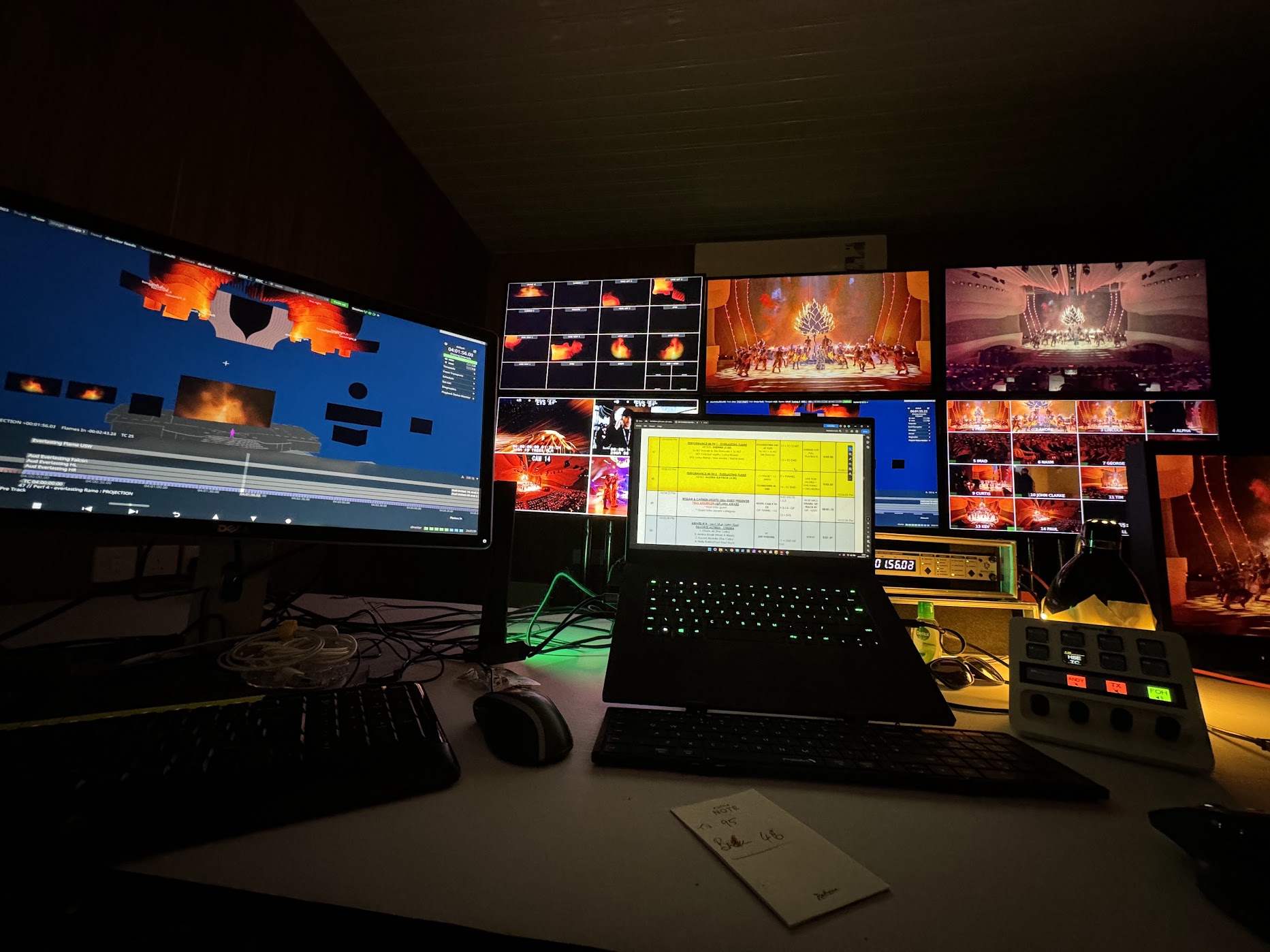
This was my programming setup, Dan Hall did some fantastic companion work patching my Stream Deck Plus to the Behringer rack mixer so I could switch timecode from local source to program source and also control the incoming program audio feed with simple button pushes.
It was great to have a bigger team this year with all of the onsite challenges we had to deal with, everyone was so capable and a Joy (excuse the pun)to work with. I was looking for images of the actual event but I didn’t take any of it complete. The final show went well and was also super long (almost 5 hours) and it was another fun challenge following along as 98% of the show was in Arabic. Lets see if were back together for another adventure next year.
THE TEAM Lead Progammer : Me Programmer : Adam Power Programmer/Lineup : Dan Gray Programmer/Lineup : Ed Joynson Technical glue for video : Pete Tilling Screens Production : Chris Saunders QED Team : Harry Ricardo Dan hall Paul Morland Ben Shepard Toby McManus Alex Peggington Steve Hardcastle
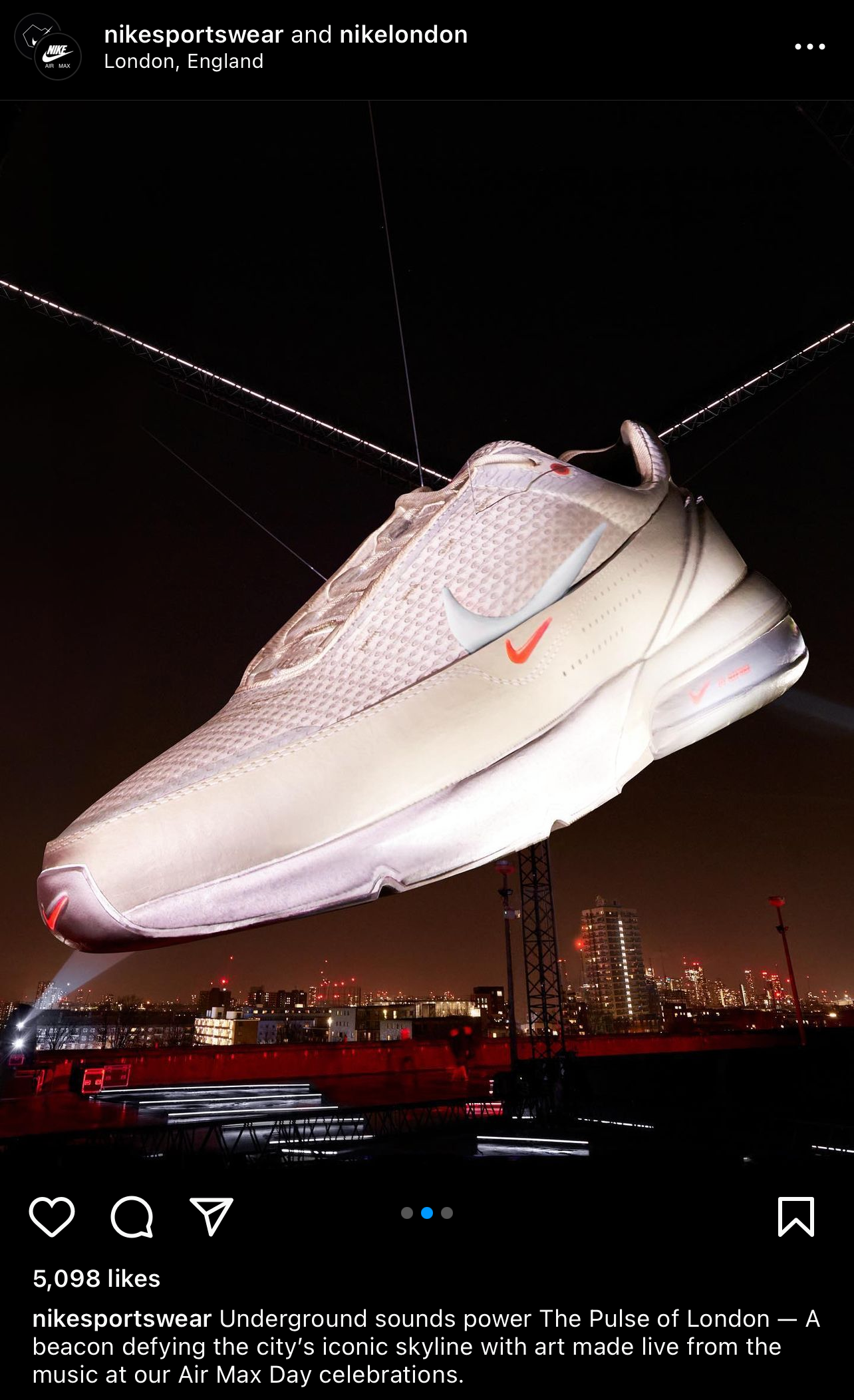
Early march I got a phone call from Pod Bluman of Bluman Associate’s asking if it was up for being involved in a projection mapping project for Nike Air Max day 2023. On the project already was Rich Porter looking after the projection study + project setup and also Lewis Kyle White looking after texturing and content on the new giant Nike Air Max were were to be helping launch for the agency Amplify.
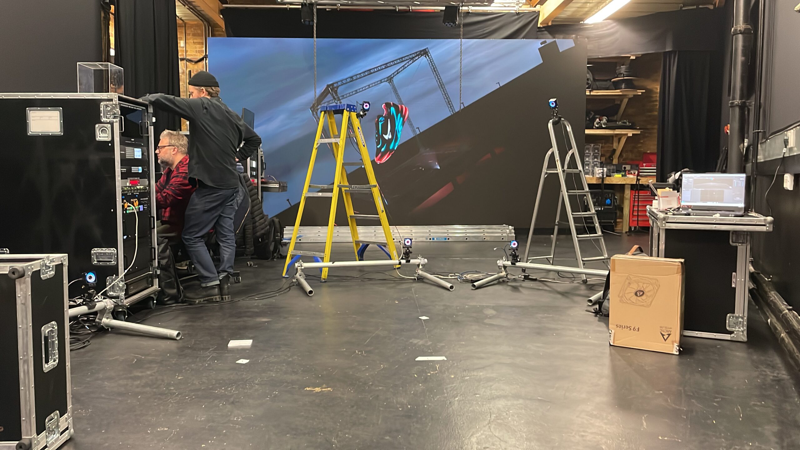
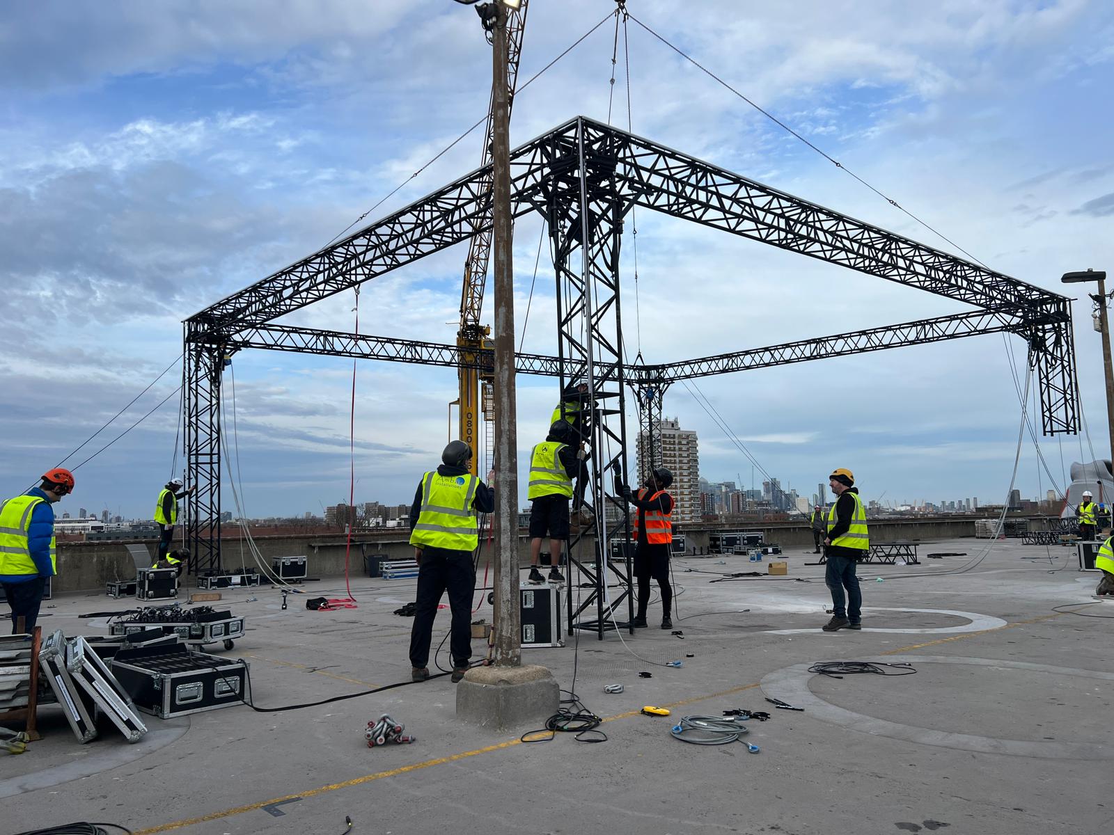
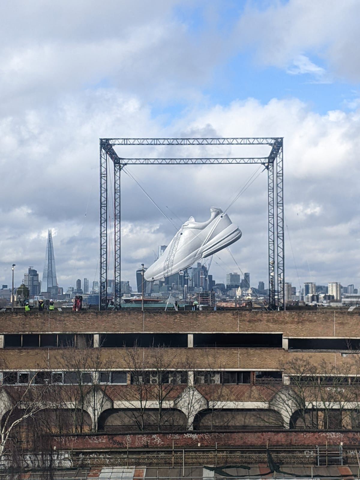
The giant shoe we were projecting onto was to be situated on top of a car park in Peckham opposite the venue where the launch party for the new Nike Air Max was to be hosted. Due to the ovation of the shoe and the forecast high winds my involvement was to help track the shoe if it was buffeted by the wind so the projection would stick to it. This was because the shoe was hung on steel cables and due to the nature of the rigging it was impossible to keep 100 percent static.
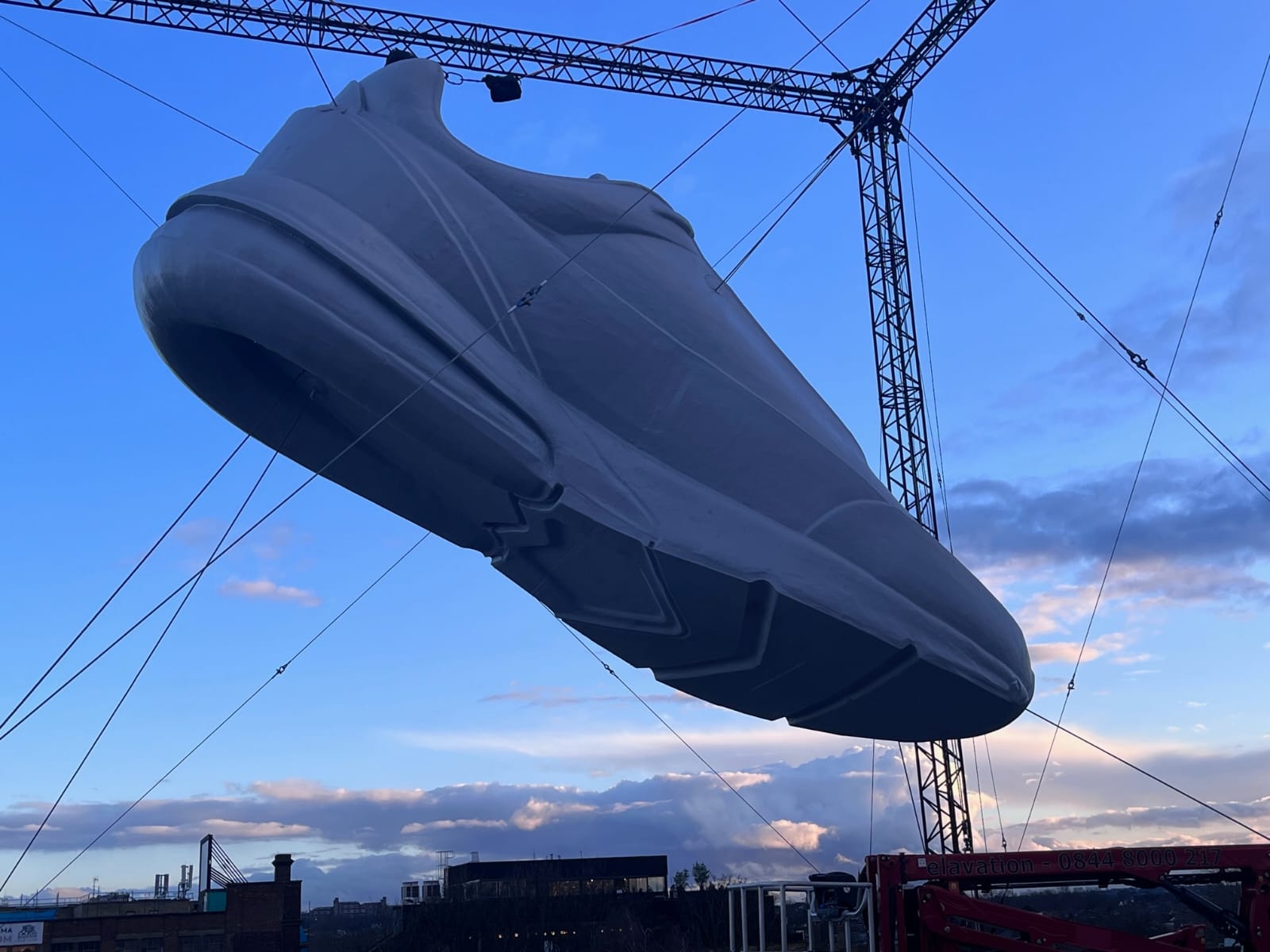
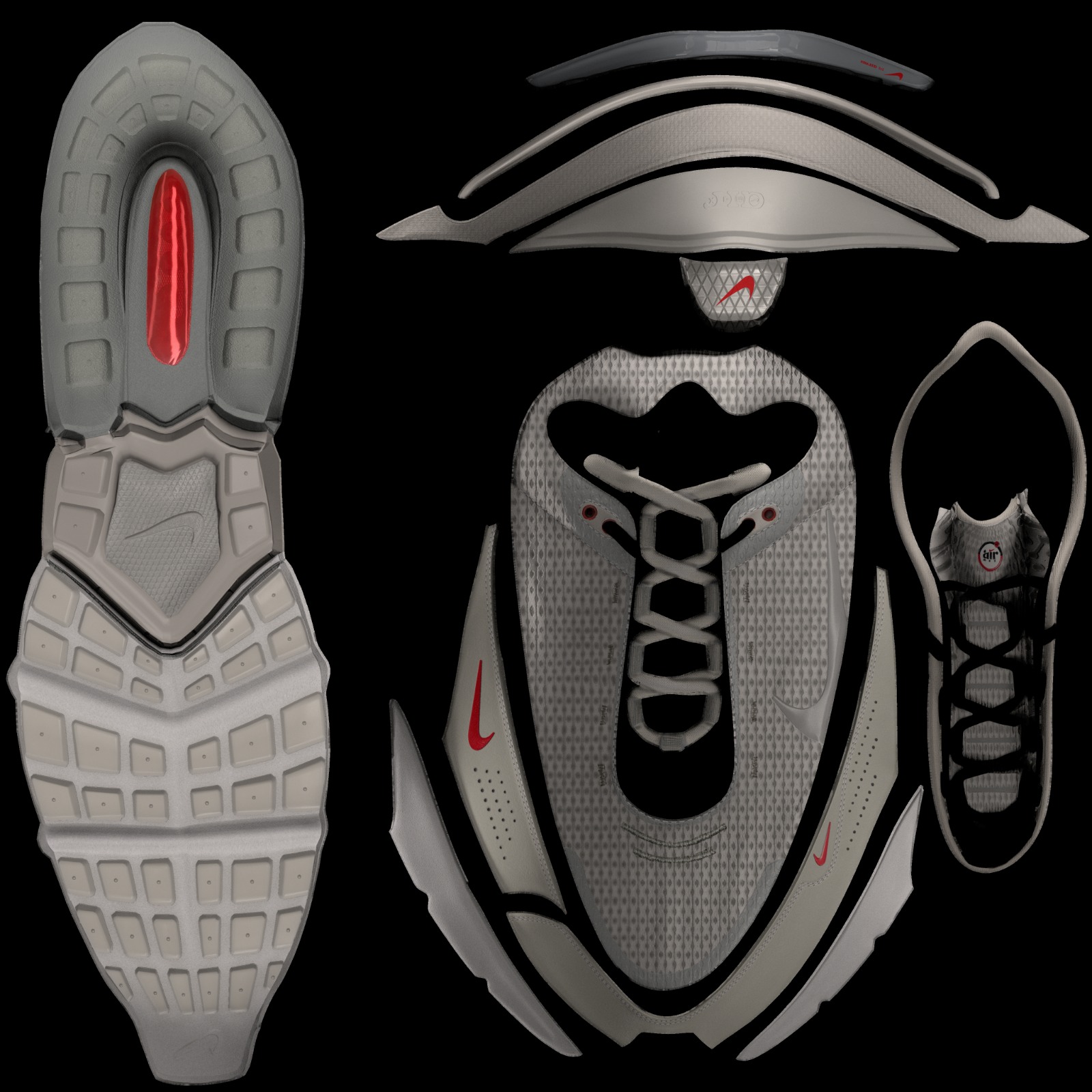
Lewis made a great job of remodelling the shoe from high poly mesh into a low poly mesh ready to be sent to Stage One to be machined and built in real life measuring and actual size of 10m toe to heel. The whole thing was suspended in the middle of a 17m cube of truss and supported by heavy steel cables. Above is the incredible texturing work Lewis put into the modelling, the fabric looked so realistic when projected on the shoe.
In the pre planning stages the guys from bright studios helped out consulting in the best methodology for tracking. In the end we all agreed that using Optitrack to track the shoe & Stage Precision to format the data in a useful way for the disguise media server to receive it was the most flexible solution
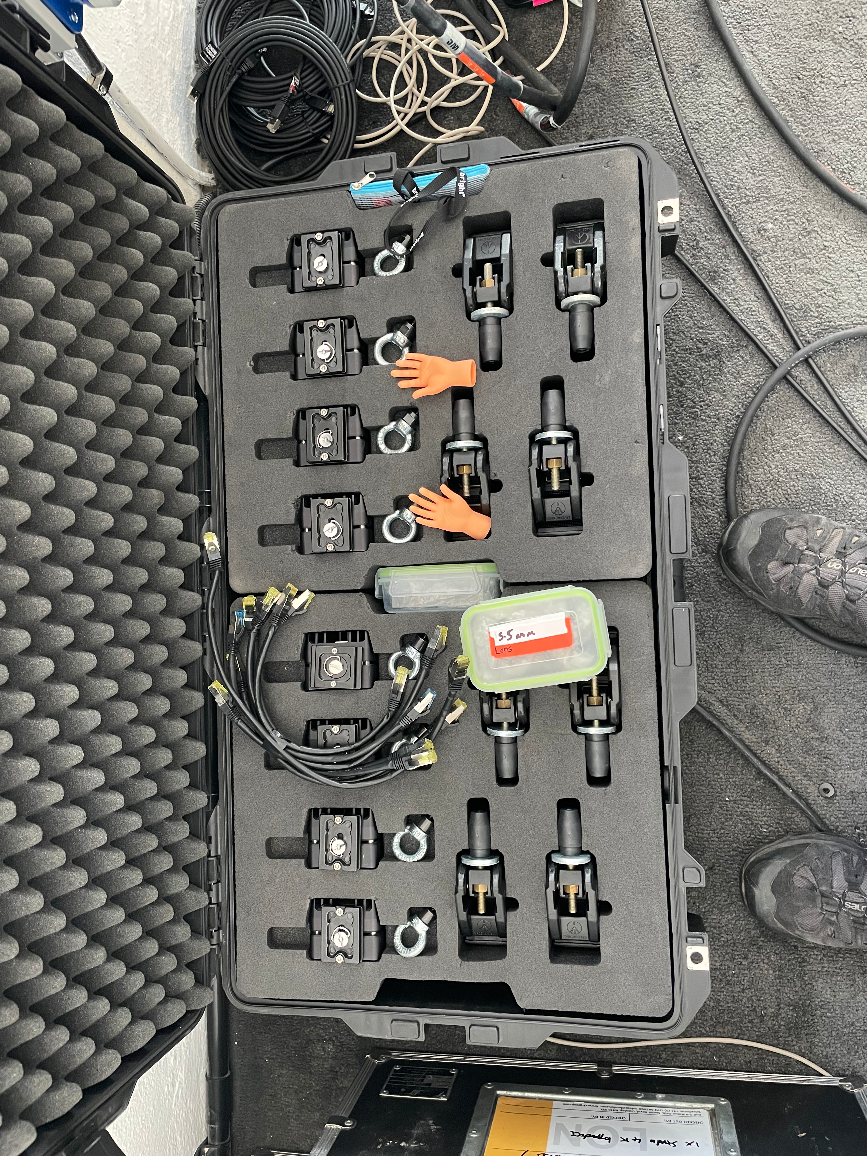
Bright provided us with an 8 camera tracking system and prior to going onsite we had two days pre production in the Bluman studio space to do some testing and work out the technicalities before going onsite. It was great to see everyone who id not seen in ages and also be joined by Ed who was programming video for the launch party across the road from the carpark.
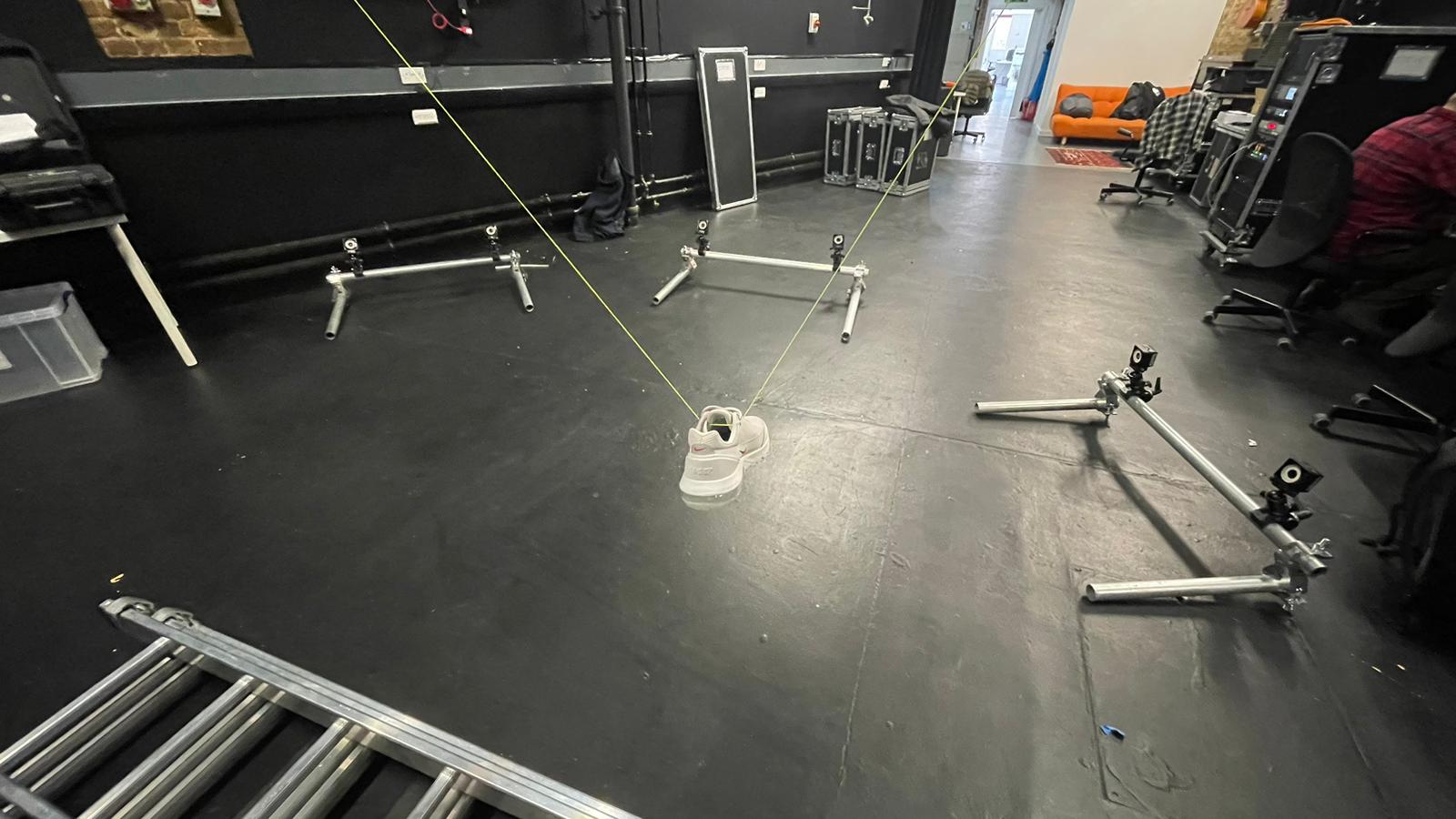
When I got the the studio space and after having a good natter with everyone who I’d not seen in ages I set up some basic rigging for the cameras. We were meant to have a 1m 3d print of the actual shoe to test but we couldn’t get one done in time, so instead Lewis decided to hang the sample shoe from the truss for the craic.
We had a great couple of days testing and working out a workflow for getting the tracking data from Motive to disguise using stage precision in the middle to align the tracking data and the virtual world. Over the weekend the team worked getting the truss and the shoe rigged ready to get the projection in and lined up from Monday.
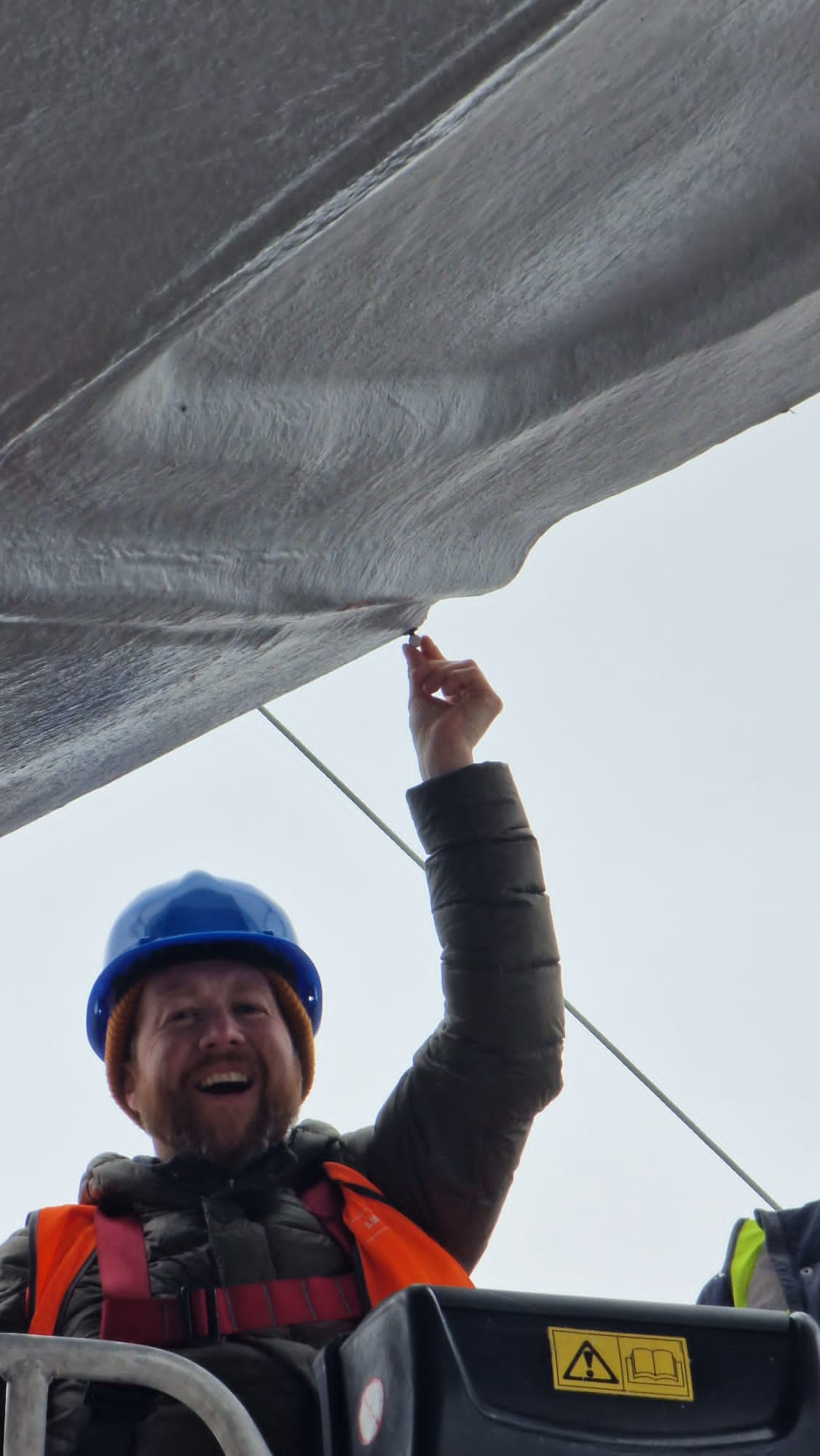
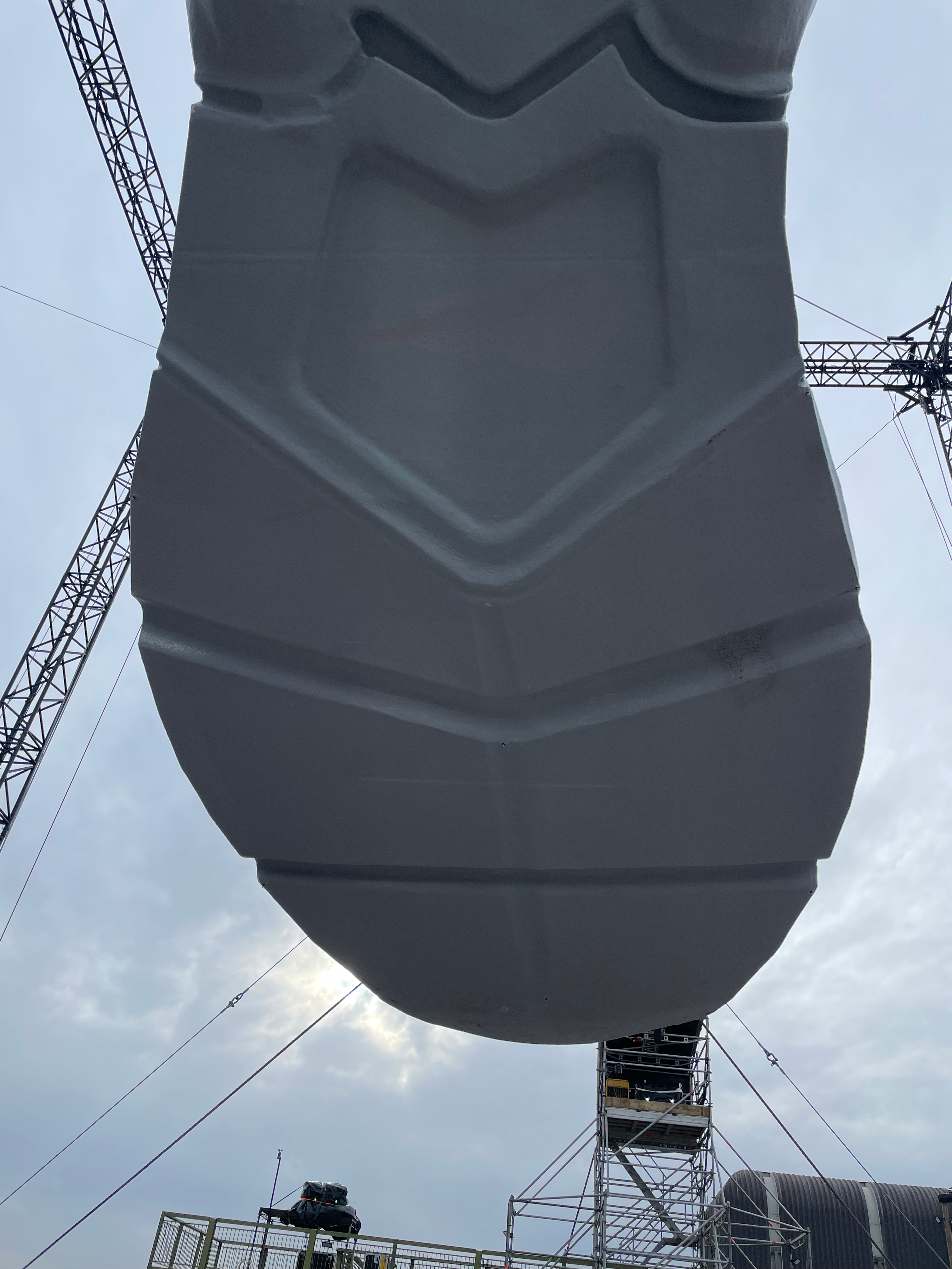
View of the shoe from the party venue over the other side of the railway tracks from the carpark which houses Peckham Levels. The first thing I had to do once getting onsite was to attach the tracking markers to the shoe, these are small 10mm retro reflective markers. The tracking cameras have a built in light which blasts out infrared and the markers reflect the infrared light back to the camera. Using multiple cameras looking at these markers 3d map of the markers position is formed.
I covered the lower part of the sole of the shoe which could be reached with a small cherry picker with seven markers. This was enough for the camera’s to pick up a large enough area and detect the movement of the shoe.
This below is a reconstruction of the markers attached to the shoe in the Motive software. Due to the nature of the system using infrared light we couldn’t calibrate the system or check if the cameras could pick up the markers until sundown. For a couple of the cameras we were close to the maximum distance limit for the system but as we did the first calibration of the system they picked up pretty well. I ended up moving some cameras around from the original plan to get better coverage, and after some settings tweaks we had the tracking data come in really well.
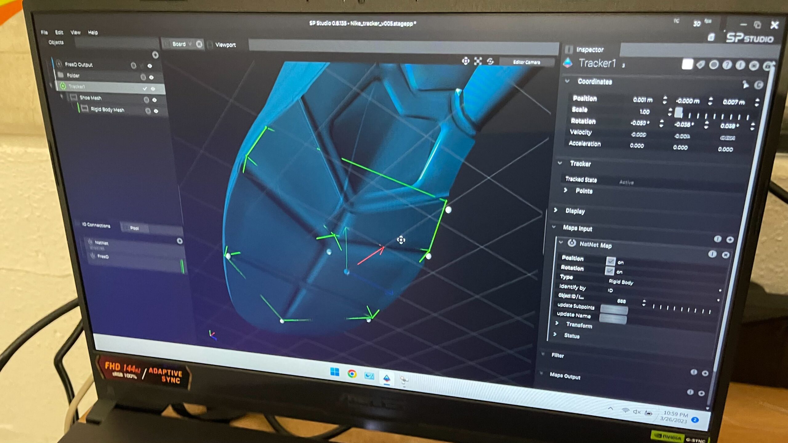
Once I had the tracking data set up I switched on streaming in Motive so I could pick up the NatNet data in stage precision. I was going to try and use the world align tools in SP to align the tracked points to the fixed points to where the projection on the shoe was calibrated too but this didn’t quite work with this setup and I’m told this is fixed in the current version. Instead I manually did the XYZ offsets to match the tracking data to the static position of the shoe which worked a trick, after all the offsets were correct i passed the tracking data to disguise as a FreeD tracking data packet which Rich attached to the shoe object. The whole process of lining up projection then offsetting the data relied on weather being good as the shoe had to be static for the first initialisation for this for it to work, luckily we had enough moments of good weather for this to happen.
In the end everything came together and as the shoe was buffeted by the wind the tracked data passed to the disguise project and helped the projection stick to the shoe, a great success. In addition to that it was great to catch up with a load of people id not seen in ages and have a really good time in Peckham over a few beers after work.
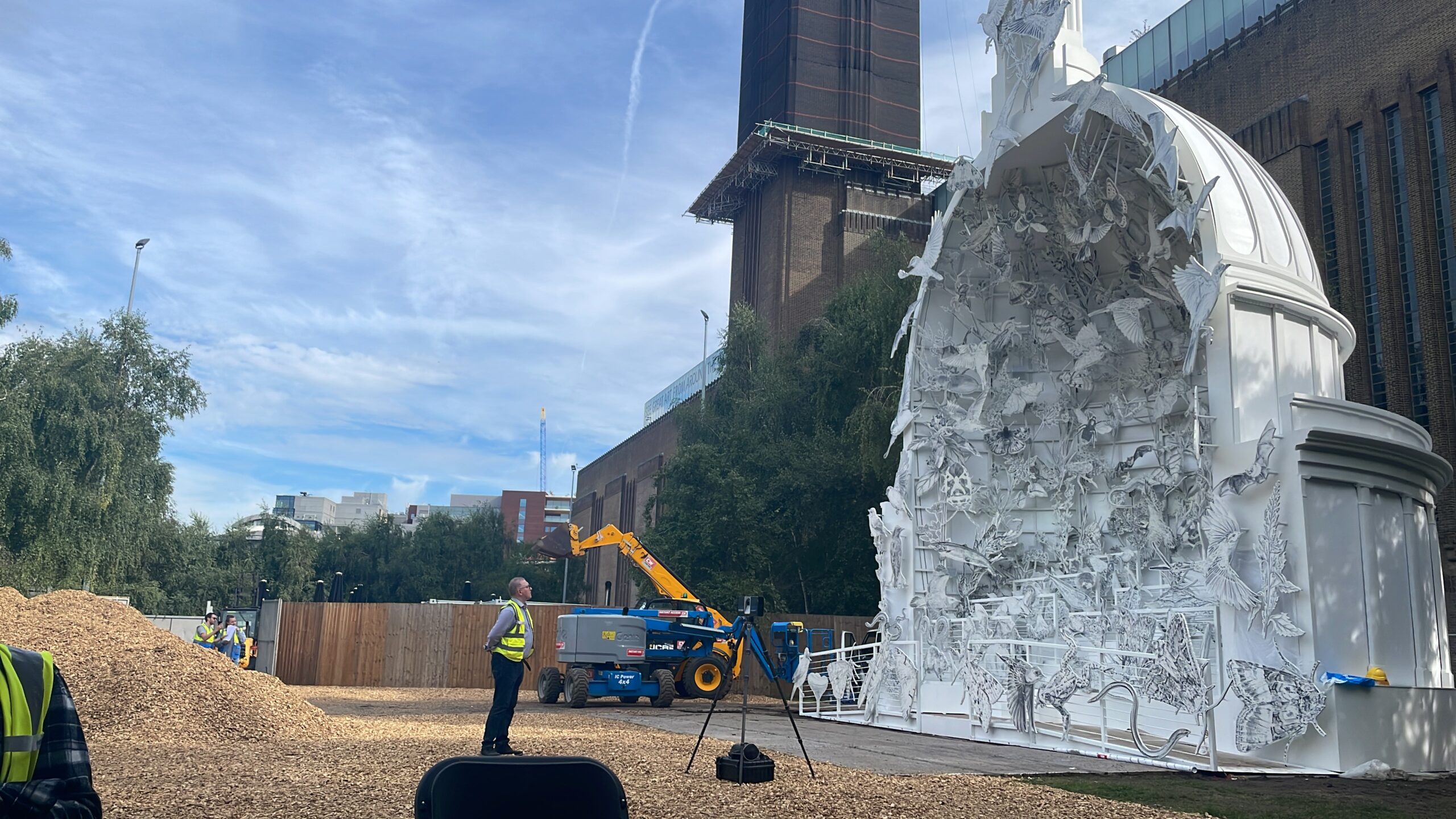
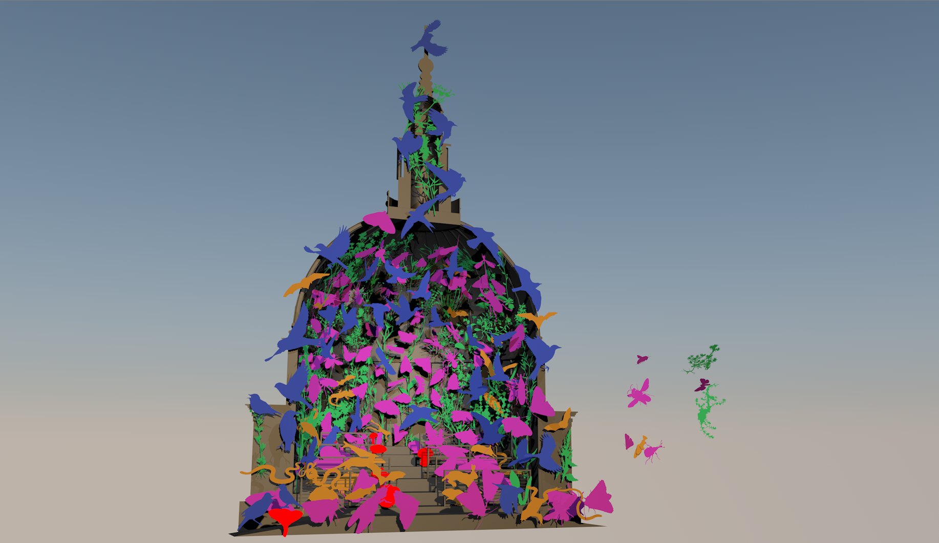
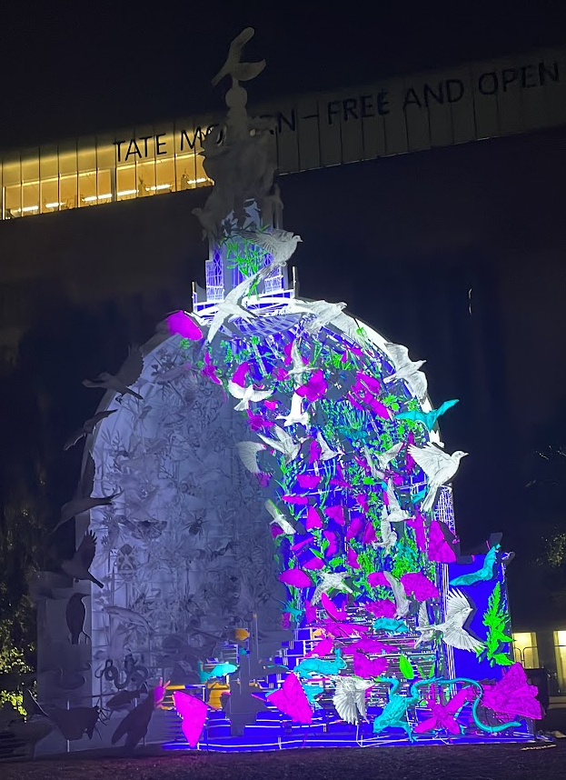
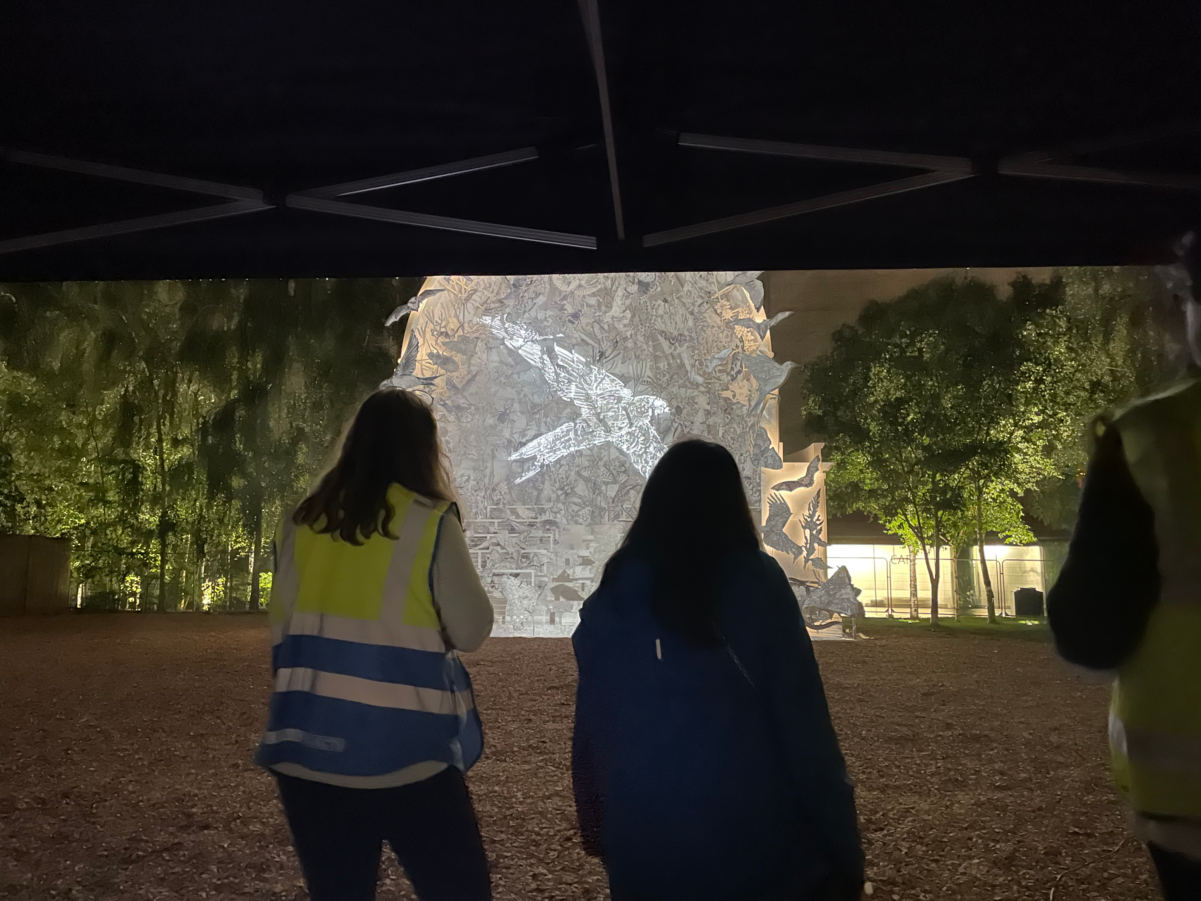
Earlier this year I was asked by Luke Halls Studio to work with the team on a project by Es Devlin called come home again. The piece / sculpture is designed to bring awareness of 243 at risk species of nature and wildlife throughout the UK. I was brought onboard to look after the work flow to projection map onto the sculpture from generating the UV templates for the animators through to laser scanning the sculpture and remodeling elements to enable accurate projection lineup.
Sculpture during the day
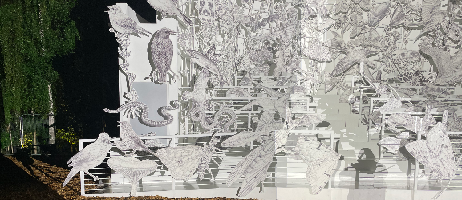
The sculpture was built by Stageone based on the architecture of the dome of St. Paul’s cathedral and was adorned with cutout drawings of the 243 species all had drawn by Es. In addition to the projection element there was also a choir performing with a sound scape in addition to Es taking about the species a la Marks and Spencer style advert. And lastly there was a lighting element thrown in for good measure to backlight the decoupage style set pieces.
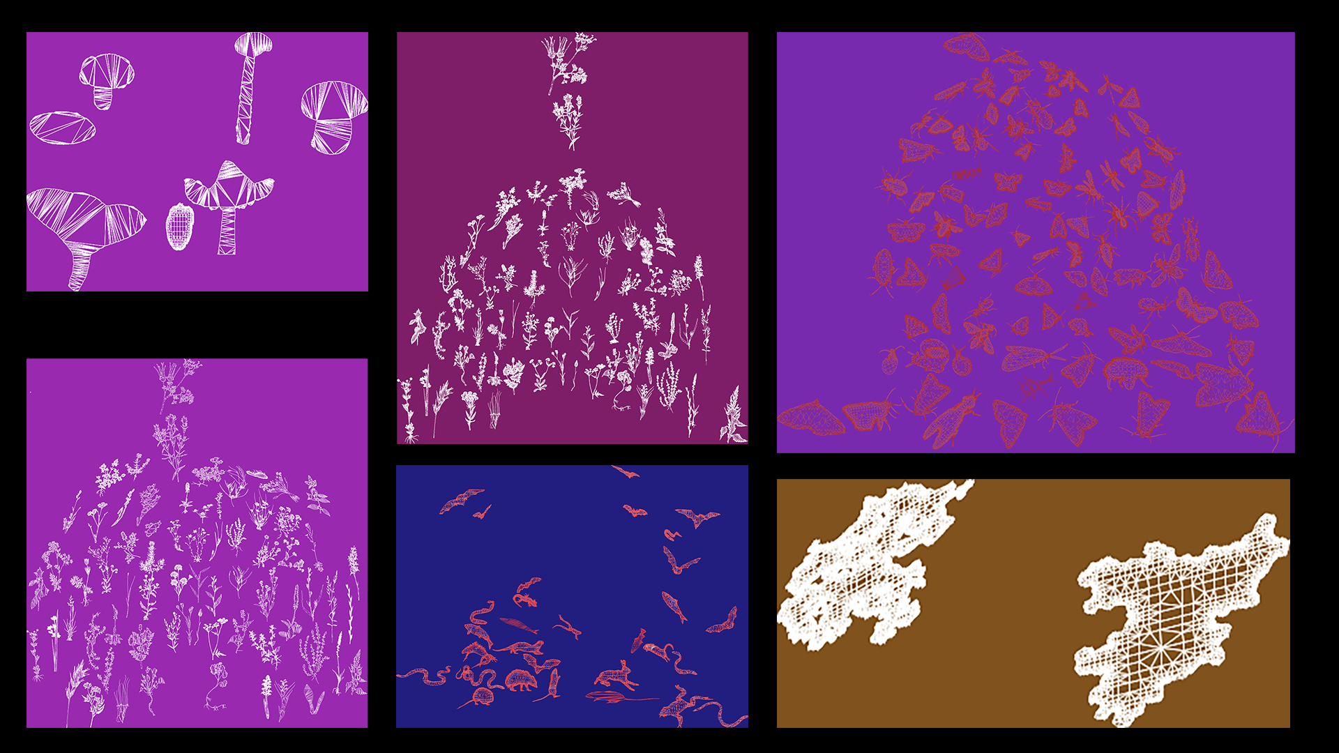
The whole process started with myself receiving a Rhino3d model of the sculpture and having a chat with Charlie who was leading the video design on this to figure out how to breakdown the model and UV it so the content templates would be flexible and also easy to decipher. The model as split into constituent parts consisting of the Base model to which all the species were mounted and each species split out, these were, lichen, birds, insects, mammals, plants and fungi. Each species was given its own UV map which when all collected together created the map for the whole projection mapping of the physical structure.
Some of the multiple UV for content creation
The rhino project was pretty busy, not only did it have all the 3d bit that we needed it also included every single nut, bolt, mounting bracket, EVERYTHING. This took quite a bit of cleanup to split out the parts we needed and the parts we didn’t need and reduce the model down to few enough polys so the media server software could run smoothly. This was a really long process and I’m still trying to find more streamlined ways to make this quicker. It was only after isolating and grouping the species and the structure that I could generate the above UV maps from the cleaned up 3D geometry.
C4D model generated from the cleaned up rhino file
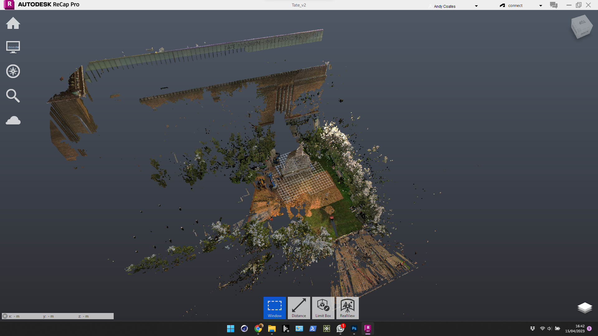
At this point we had two versions of the sculpture, one was the virtual 3d model and the other was the as built real world structure. In my experience, temporary structures of this scale and complexity are very rarely the same as the drawings they were built from. For this exact reason, a few years ago, I invested in a laser scanner (Faro s70) to specialise in laser scanning for projection mapping. Once the structure was finished I got my friend and colleague Paul to come down with the scanner to get an accurate 3d scan of the as-built structure.
Wide view of the scan data captured
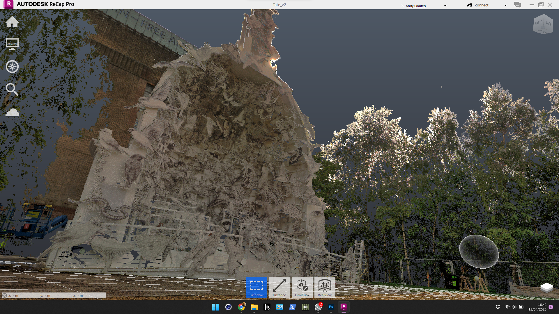
The laser scanner basically takes millions of measurements from a point and builds up an accurate representation of the surroundings called a point cloud. Once the data has been captured and processed into a point cloud viewing software of choice you can move the virtual camera around the 3d scene and view the capture from any perspective which really pleasing to look at. Below you can see the limits of the capture which is 70m so that’s why some of the background elements disappear into the ether, anything outside of a 70m radius of the capture is lost.
Closer view of the point cloud data from the scan
From the point cloud data I spent quite a bit of time cleaning this up so I only had the data of the structure and the animal cut-outs to then turn into a mesh for use in Cinema 4d. From the real world scan and the existing model I could then overlay the scan data on top and see how closely things matched.
Clean mesh being placed on top of the scan mesh
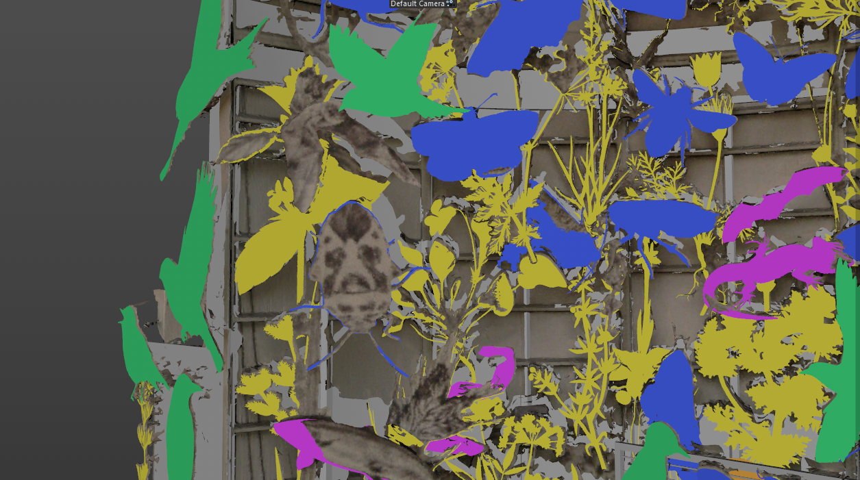
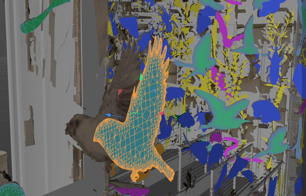
As expected the CNC cut structure of the dome matched the scan data incredibly well. When it came to matching the animas, insects and mammals etc almost everything. Needed a nudge into place, not by much most position and rotations were off a little and some cutouts were swapped around completely. It took 2 days to painstakingly check and tweak the position XYZ and rotation XYZ do each of the 243 species until each position matched the scan data.
Moving the position and rotation for each species
Once all the 3d to scan data was done i generated different color lineup grids for each species and a wireframe from the 3d mesh to help with the projection lineup. CT were providing the projectors for the event and Nico was in charge of servers and lineup. With the scan and the modeling i was expecting that it should be straight forward, but with all these things you never really know until you you get all the hardware software and structure together. On the first projection alignment pass it popped straight in, there was no reason for me to double that it was going to “click in”
I did an initial test with disguise and quick cal to make sure the whole process worked than I handed it over to Nico to finish and tweak the alignment to which he did a great job. All along side this Zakk from Luke halls studio was programming the show on a parallel copy of the project, so once we had a decent alignment we were able to preview bits of the show with rest of the team.
It was a great project to work on and great to be working with mates and colleagues who really care about the job. I never actually got the chance to see the finished show as i had to leave London onwards to the next job, on all accounts and from pictures it looked great :).
Last I’ve was out snowboarding with friends was January 2020, not long before the world went to shit and little did we know that there would be limited opportunities to do it again until 2 years later.
It was around mid January the small WhatsApp group of us so went boarding at La Clusaz in 2020 started chatting thinking about getting the gang together and hitting the slopes again this year
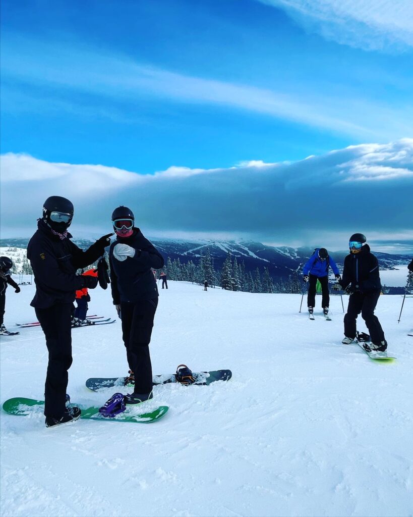
Kristaps, James, Matt & Pillerin at one of the peaks at La Clusaz (Jan 2020)
I booked a place in Åre Sweden that Kristaps found on Abnb which was more than big enough for all of us but unfortunately this year not everyone was able to come due to work commitments and timing with the spontaneous decision to go.
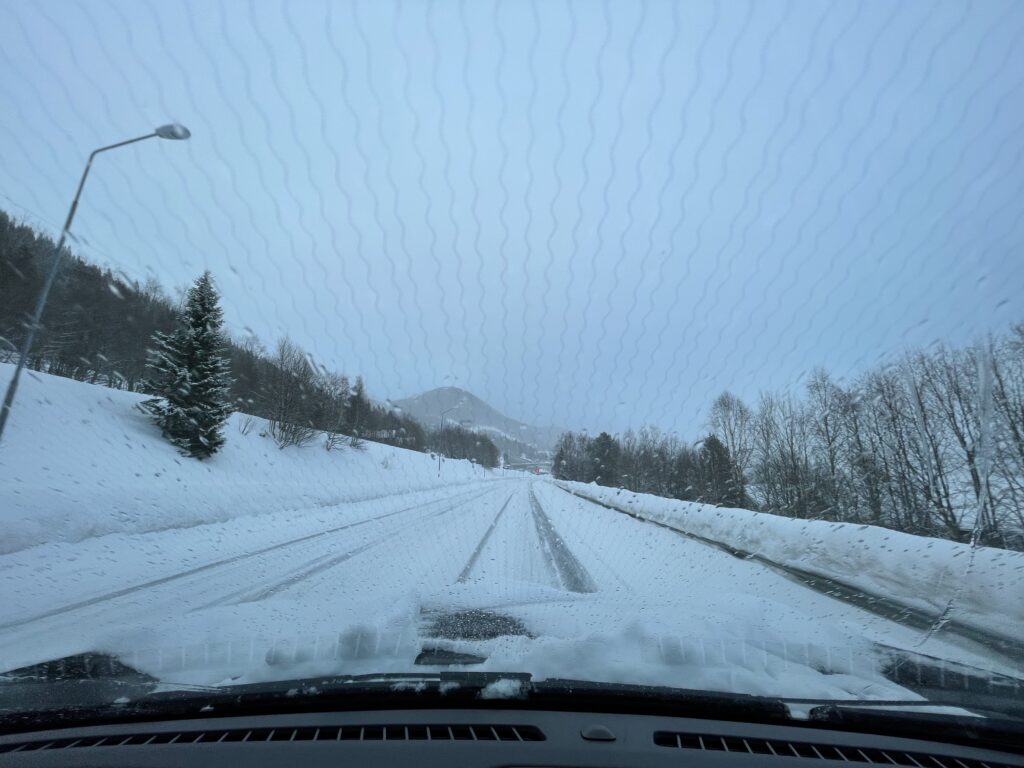
Swedish driving in the winter.
In the end there was only 3 of us this year, we met up at Ostersund airport and we all jumped in a hire car for the 90 minute journey to Åre. It’s the first time I’d driven in a vehicle with studded tires and on roads covered with so much snow so it was a bit of an adventure
Pillerin, Matt & Myself
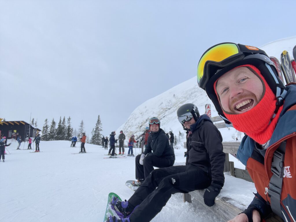
After getting some food shopping supplies for the week on route to Åre we got to the Abnb unpacked ready for the following days boarding on the slopes, we were at the Tegefjäll part of Åre and the slopes were comfortably quiet with very little queuing to get on a lift which was amazing.
In our little resort of Tegefjäll 10 mins drive from the main resort the Slopes were comfortably quiet, enough people there to give an atmosphere but quiet enough not to be crashing into people.
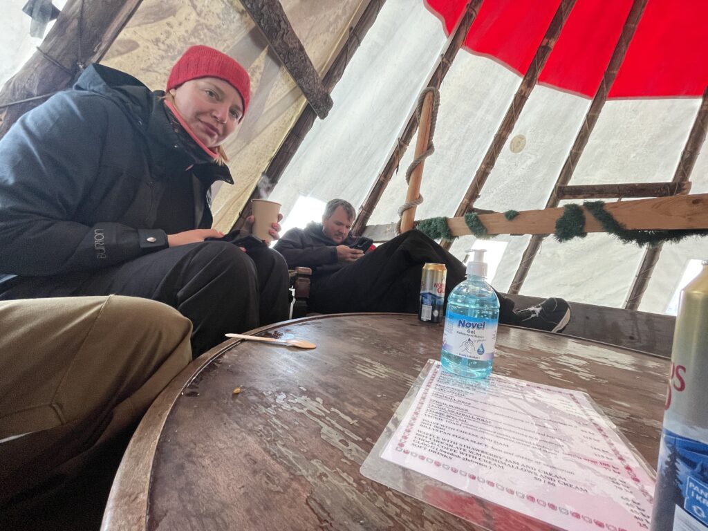
At the top of the lift from our area there was a great little tipi where we popped in a few times for a lunchtime beer and burger to replenish our energy for boarding. This little place was much more fun and cost than the more commercial eating places dotted on the slopes.
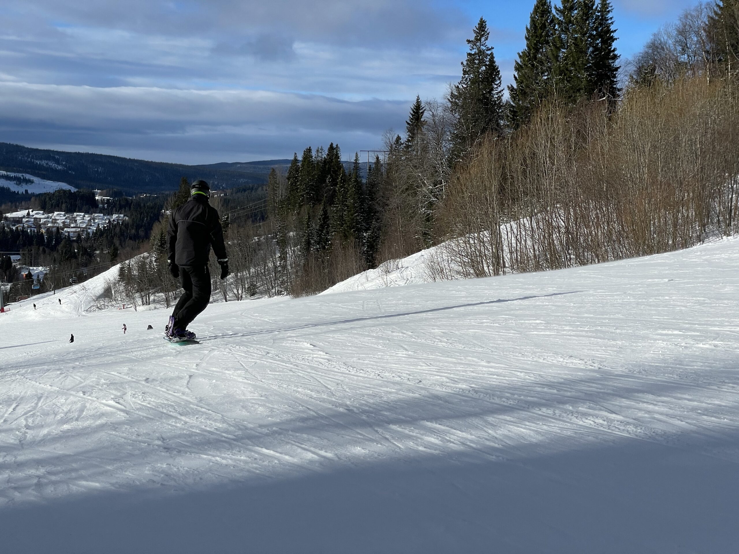
We spent the majority of the time at Tegefjäll, getting the lifts and boarding across to Duved another area linked by lifts and slopes. We easily spent a day getting the lifts, boarding across up and down, to Duved, grabbing lunch and by the tine we boarded back the lifts were closing. It was quite leisurely area and a pleasing way to spend the daylight.
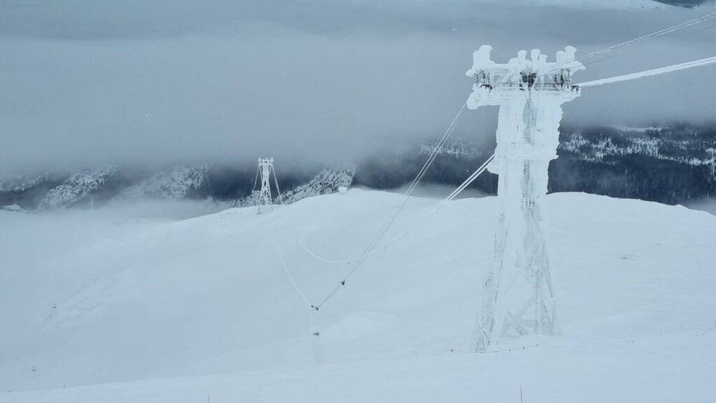
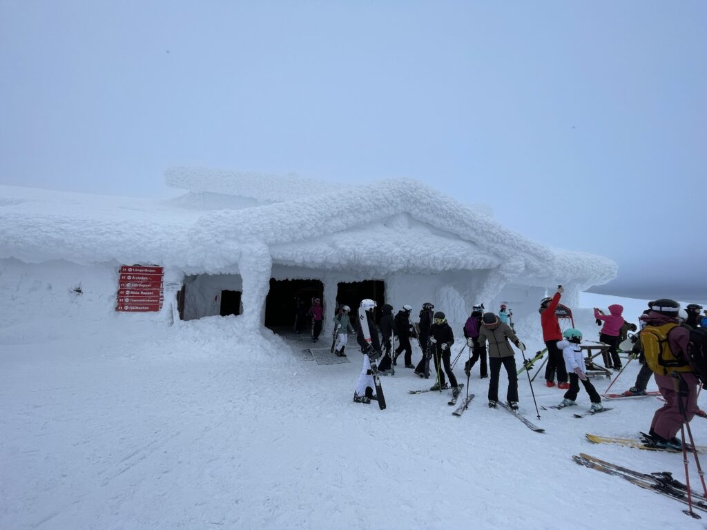
The weather was a bit hit and miss over the week that most of the lifts in the main Åre resort were closed die to wind and I think it wasn’t until the Thursday when we managed to get across to the main resorts and try the slopes there. There was quite a bit of queuing to get tot he very top but once we got there it was amazing, everything was covered in layers and layers of snow dust.
Getting down front he top was fun as there were quite a few flat parts of the run requiring a fair amount of speed to get across without having to take the board off and walk. It was so soft and powdery near the top and at some points with pretty limited visibility.
We finished the last couple of days back at Tegefjäll and had a very slow last day on Saturday as we were all aching from a LOT of boarding. We finished almost all the food we had bought for the week that evening and watched The Muppets film (2011) which is still brilliant! The whole week flew by and it was so good to be back on the slopes with friends after that last couple of years. Next trip is to Dubai working on the closing of the Expo 2020, stay tuned 🙂
Its difficult how to start this new blog post in the new year after what a fuck up 2020 was, it would be nice to think that as its a new Gregorian year its a chance for a reset and the start of a more sociable era. I’ve got high hopes for 2021 though I don’t think were going to start the climb back up to the new normality until April depending on how the Westminster circus handles the vaccine rollout.
The year ended and started off very subdued, new years eve was spent in the flat watching Netflix, drinking whiskey sours and catching up with friends on the phone and the following day tidying and having a good clear out in the flat. This was a pretty different to NYD 2020 where i was on a plane to Vegas to work with the excellent guys at Pixway on the Nissan stand at CES2020.
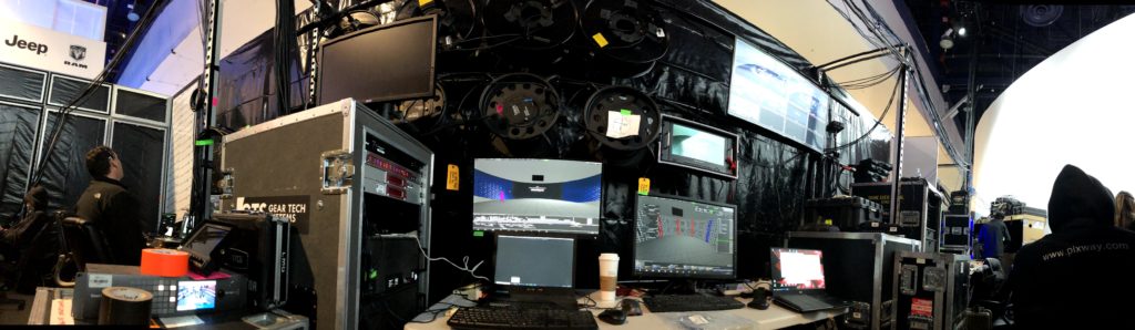
CES 2020 Nissan control room
For the Nissan booth at CES2020 we had a 16 projector circular projection surface, 8 bends and 8 overlays and we were using the disguise Omnical system to assist with projected image alignment. I’ve used Omnical a reasonable amount since 2018 on various jobs and have a good upstanding and experience of what s required to make it work well. The more accurate you can make your geometry in d3 the easier the process will be, for the CES booth we had a CAD model of the stand but generally on temp structures and especially a big cylinder which we have here there will be some discrepancies in the build and the cad. Before starting any projection calibration, Francisco and myself spent a good couple of hours taking a survey of the projection surface with several lasers and tape measures and I reconstructed the ad model to as close to the real world as possible. From the top don the projection surface was more like a oval than a circle after doing a survey, fixing these small solid foundations makes a HUGE difference further down the line.
Pre opening line-up checks
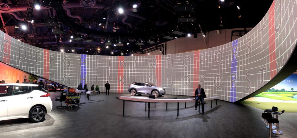
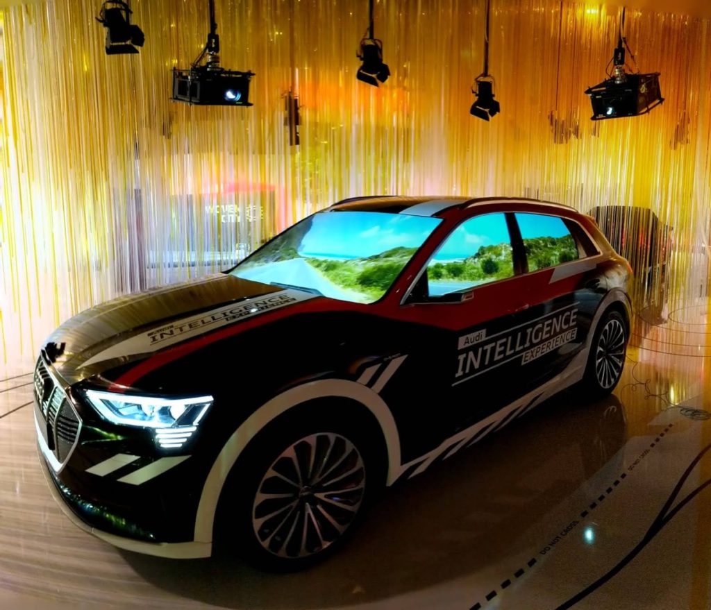
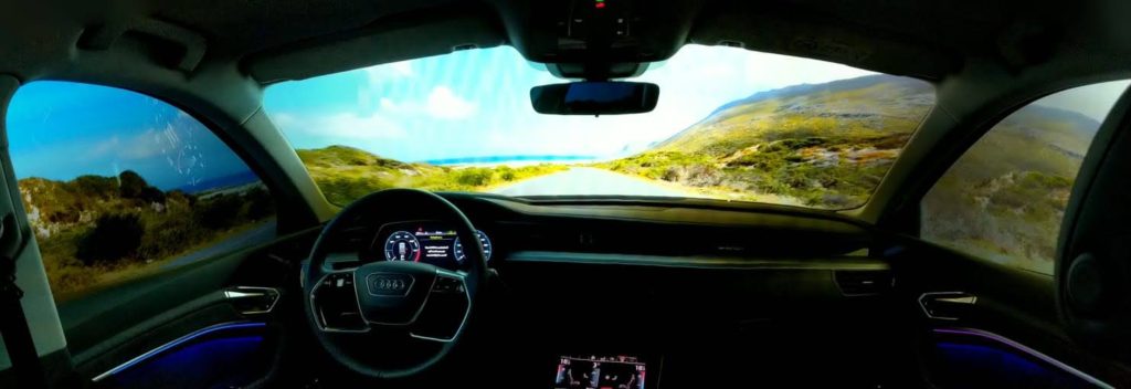
We had I think 9 shows a day at Nissan over the period of CES and all went well with the client being swimmingly happy! Next to us Manuel was looking after the Audi booth which was beautifully designed. He spent hours programming the d3 timeline so the projection onto the frosted windows of the car responded to the car console stick and button operations, it was a really nice interactive part of the stand.
Audi CES 2020Inside the Audi virtual driving experience
Outside the convention centre Paul and Delaney were looking after BMW, which was a custom built experience in a structure in on of the parking lots of the convection centre, it was incredibly slick just as you’d expect from BMW. Ed was over on Adaptive but I didn’t manage to get any pictures of his setup.
bInside BMW CES 2020
It was a good few days supporting the shows in Vegas and as allways, so nice to catch up with everyone over Tacos and Beer!!!! <– This place is amazing.
After the shows were over LAAAAAAD’S!!!!
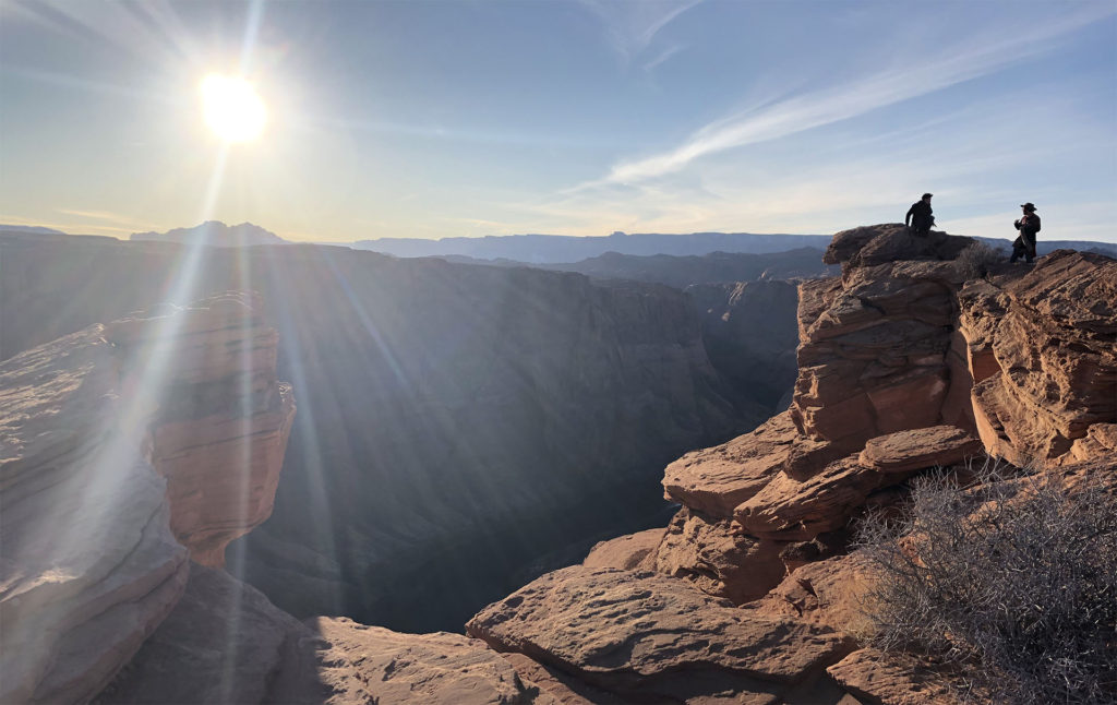
After the shows I stayed on in Vegas for a few days and one of my best mates Marley w as int he states for a few weeks and came to meet me in Vegas for a ROADTRIP!!!!! We hired a Jaguar F-type and after a chat with my American friend Charles about which part of the Grand canyon to visit he suggested Horseshoe Bend so we took his advice, stuck it in the sat-nav and headed North !
Marley in the Driving seat near My Camel
It was a fantastic drive each of us taking turns, roof down, hat and scarves on as it was petty cold once we left Vegas, i think it was around 16:00 when we got to the parking lot and then another 20min hike across the canyon get to the iconic site. There were quite a few people there and we spent about half an hour just wandering round taking photos and admiring the landscape, it was so worth doing the long drive to be there and take it all in.
Horseshoe Bend
After leaving Horseshoe Bend we stopped off at Glen Canyon dam to sight see just before last light. From here we headed back towards Vegas with the intention of finding a hotel on the way, but no real plan. We past a load of motels but decided to carry onto a town called Flagstaff we saw on the map. Upon turning up the street and seeing the sign for the Hotel Monte Vista we knew this was the place we were gonna stay. Its such a beautiful old building and our little venture round town for food and beers really made me want to go back there sometime.
Flagstaff January 2020
I wasn’t sure how to start the first blog post after so long and its just kind of evolved into this which I think is a good start. Stay tuned for next week where ill be adding another post about current ramblings and possibly a lookback to 2020. Stay safe everyone.
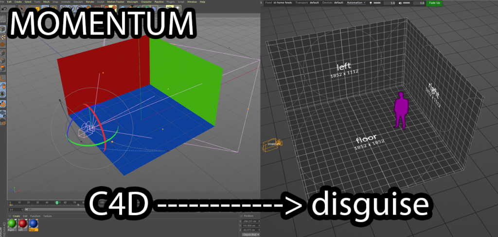
INTRO Momentum is a Cinema4D rig to output camera positional data in the StypeHF format over a network. This is aimed at the pre-production workflow when using disguise XR
BASICS Momentum is packaged in a simple c4d project and consists of a Xpresso tag and a python script to output the data in the StypeHF format, not all of the StypeHF fields are sent by momentum we only send the following, packet number and time code omitted.
Poz X,Y,Z
Rotate X,Y Z
FOV X
Aspect Ratio (This is forced to 1.7777 this only works in HD)
Focus (This is default to zero, momentum does not take into account zoom data)
Zoom (This is default to zero, momentum does not take into account zoom data)
K1 (This is default to zero, will be overridden by disguise)
K2 (This is forced to zero, will be overridden by disguise)
PA Width (This is default to 9.59 standard)
Centre X (This is default to zero, momentum does not take into account zoom data)
Centre Y (This is default to zero, will be overridden by disguise)
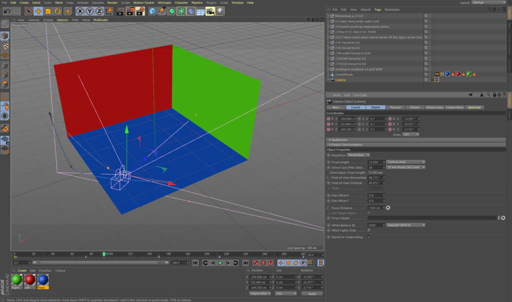
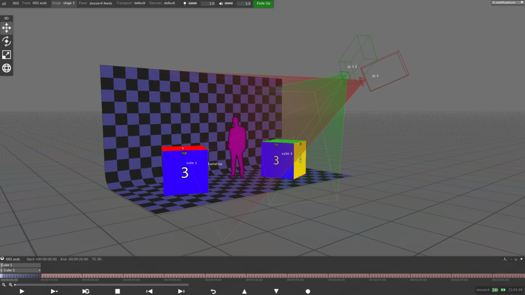
MOMENTUM First glance The above screenshot shows what you will see when opening Momentum, this is a basic scene with a stage and some camera positions key framed in the timeline. After hitting play the tracking data will be transmitted and any changes updated in real time upon pressing stop the data will stop being transmitted. Each packet is transmitted per frame so to adjust the packet rate please change the frame rate of your c4d project. Note that this is not explicitly locked to the frame rate so heavy scenes will experience a drop in frame rate but low poly scenes on a good computer will be smooth.
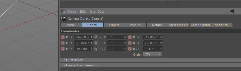
AXIS Rotation This is tested to be compatible up to disguise release 17.3 (pending) and the XR Beta branch. The axis rotation order must be set to ZXY as shown in the screenshot below for disguise to pick up the data correctly and handle roll correctly.
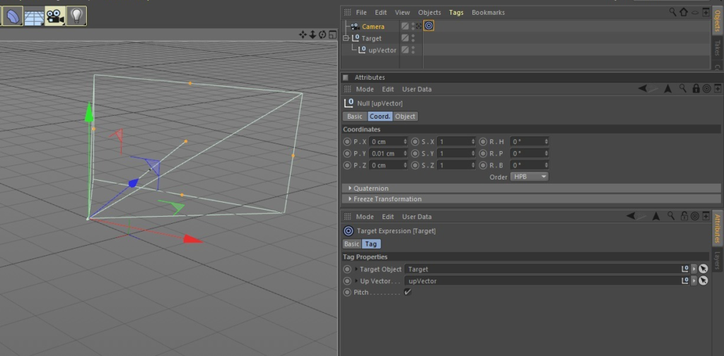
Target Tag Because of this axis order the Target Tag in cinema will behave strangely, I’m working on a fix for this as of 12/06/2020 Solution found for the target tag see below image and description 15/06/2020
To get the target tag to work correctly with the required Axis rotation you need to add in an “Up Vector” null. Make the Up Vector null child of your target null or object and position it 0.01 cm on the Y axis in relation to your target and add this to the target Up Vector field.
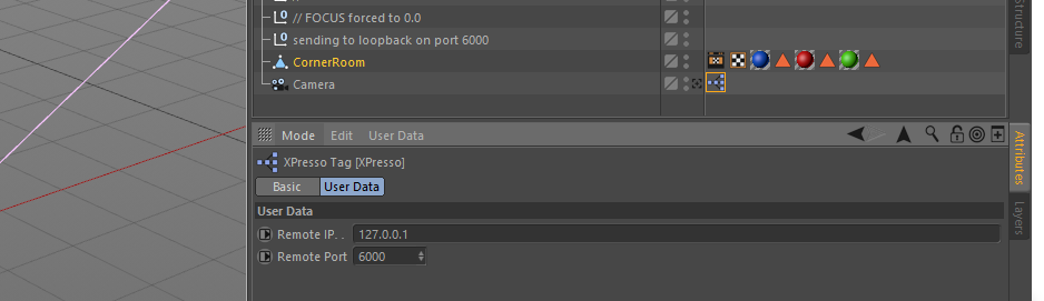
IP & Port Number Clicking on the Xpresso tag will open up a window with the option to send the positional data to a specific IP address and port number. Please not this isn’t tested across large networks so if you experience any issues please feed back via the email at the end of this post
Credits Thank you so much to the following people for help with coding beta testing and fault finding of momentum, without this teamwork non of this would have happened Karl Bromage – Studio One Four Andreas Culius – nocte designs Rich Porter – The Hive & YouTube Channel Scott Millar – Longer Days Lewis Kyle White – LKW
DOWNLOAD MOMENTUM Download Momentum from GitHub via the link below, any comments or issues please get in touch via andy(at)andy-coates(dot)com https://github.com/andydenniscoates/momentum
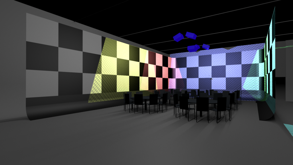
Hello everyone, following on from the previous blog post I’m going to be running through building from scratch the above disguise project and reasons behind the methods. Im going to be continuing this series in Cinema4D R21, I found a bug in R22 which breaks my workflow, I’ve spoke with Maxon and waiting fro them to fix it. The cinema project and relating assets for this post can be downloaded here: 002 C4D-d3_workflows
I’m primarily going to be concentrating on the 3D project build up here and less on the disguise side of things as there’s some excellent training resources out there already. I highly recommend you check out my good friend and colleague Rich Porters YouTube channel for disguise tips and tricks.
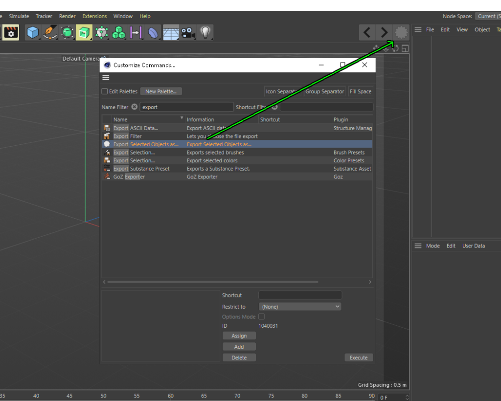
Lets get started by adding a really useful button to your cinema workspace and this is so we can export objects as separate elements. Using the export option in the file menu only allows us to export everything in the scene as one object and we want separate elements. Adding this button will allow you to export selected objects individually.
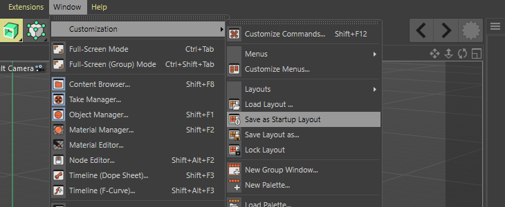
Fist of all hit Shift + F12 to bring up the customise commands menu ins in the search bar type “export” and this will narrow down a list of export commands. We want Export Selected Object as..click on this and drag it on to the tool bar. Once you’ve done that, save as startup layout as show before so the button stays there on restart. Its currently greyed out and that’s because we don’t have an object selected or any objects in our scene.
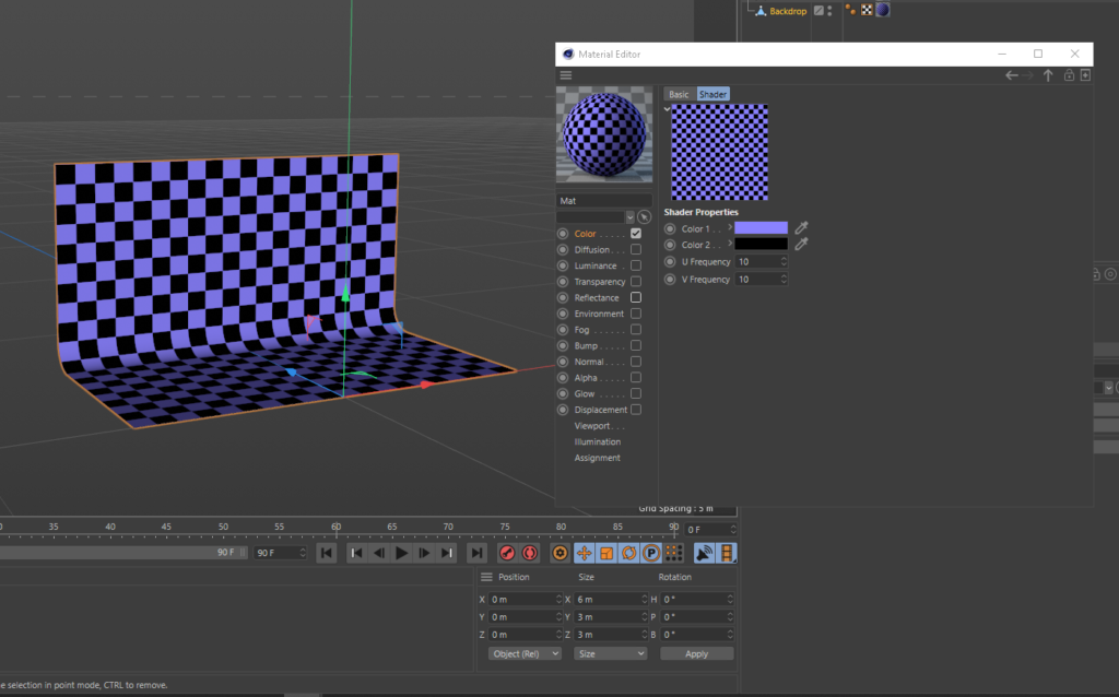
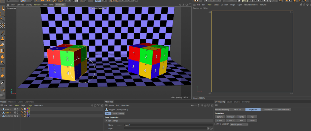
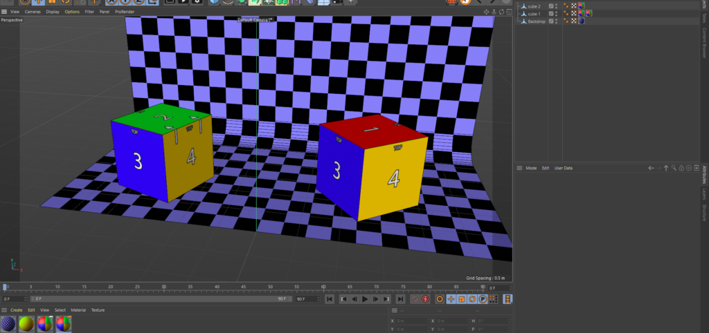
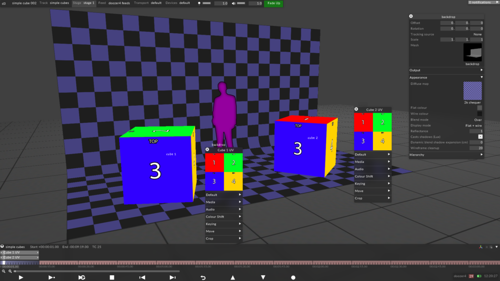
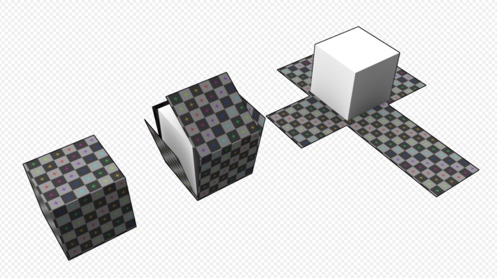
What the audience can see So the scenario is that e have a small stage and 2 cubes onstage which are projecting onto, the audience are in front of the stage theatre style and can see the forward facing parts of the cubes and the tops. This is always my starting question when speaking with the creative team in the early stage. In this case, in our 3d scene we only need the parts of the object which are going to be seen by the audience and we can focus on making the best use of the UV space, theirs no point in wasting good UV space on a part of the object which isn’t going to be projected on. I always like to have the venue stage in my scene as its a really good reference eve if its not going to be projected onto, and it makes things look nice. Make a stage like below, 6m wide 3m deep and 3m high, easiest way to do this is make a cube to those dimensions and delete all but the bottom and rear face, I then positioned the downstage centre of my stage to 0,0,0 in my scene. If you want to skip this part use the backdrop.obj from the assets download above.
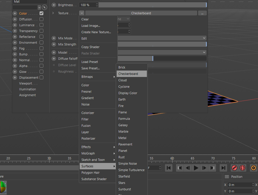
I then created a new material and selected the checker board from the surfaces menu in the materials options and then double click on the thumbnail to bring up another window and set the colours and amount of squares to your taste.
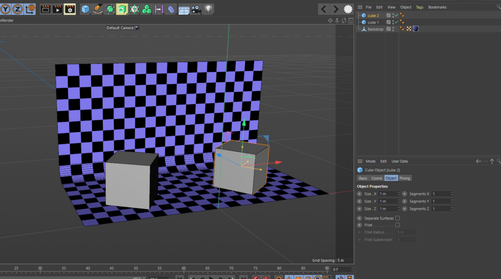
Now we have our stage setup lets make a couple of cubes, we could make one and duplicate it but making 2 is good practice and each will have a slightly different associated UV. Next create 2 cubes and make them both 1 meter x 1 meter x 1 meter and place them in your scene like below, make them editable by selecting them and hitting C on the keyboard.
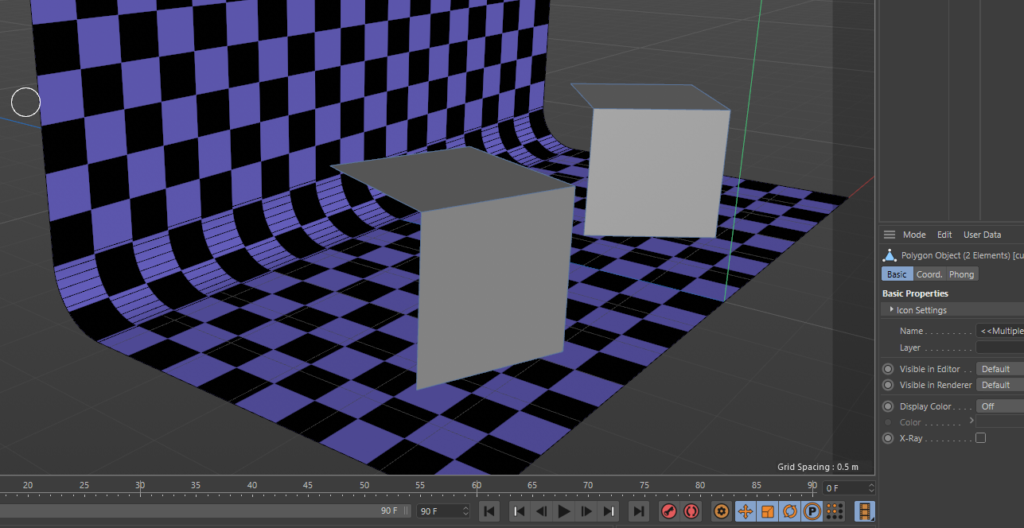
now all we need here is the front faces of the cube, only the faces which the audience will see and the projectors are hitting. The quickest way to do this is make sure your in polygon selection mode, select the faces you want then hit the keys U then I then delete. This will invert the selection and delete the rear faces which we don’t need, your scene should look like the image below.
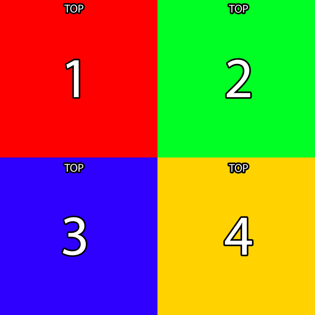
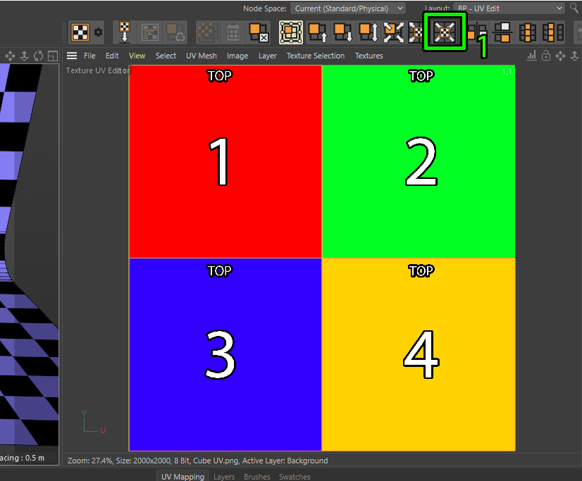
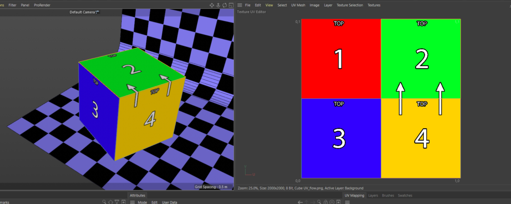
Now we have put two cubes and know the dimensions, from here we can make life infinitely easier for ourselves by creating a simple guide for ourselves to unwrap to. we know each face is the same size so I made a simple 2×2 colour grid with numbers and text to say which way is up.
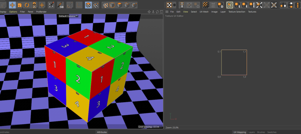
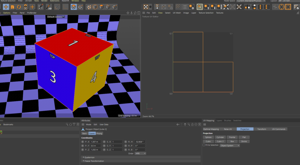
Net pull that image onto your cubes in cinema and jump into UV layout. NOTE: I found a bug in R22 with the fit to canvas command so ill be showing this in R21 and again update this to show the R22 method once Maxon fix the bug. Yous shoud now see the same as below, our helpful lineup grid is replicated on all three faces on each cube this is the default UV map when you create a cube in Cinema, were gonna change this so each face only sees one of the colour quadrants.
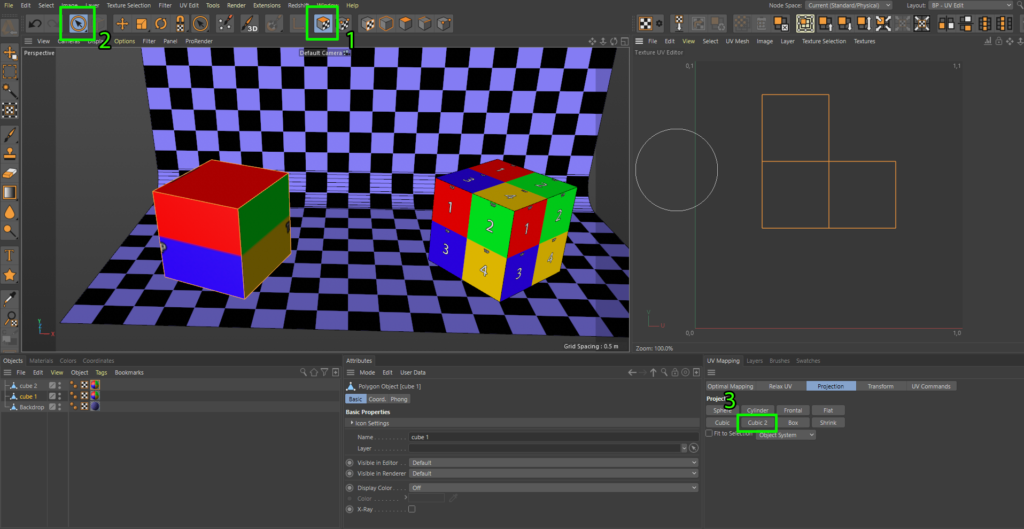
R21 UV instructions Using the screenshot as guide below, make sure your in UV polygon selection mode (1) , then choose the section tool (2) and select all the faces on cube 1 then hit the Cubic 2 button (3) and you should see the scene like this, make sure the drop-down below the Cubic 2 button is set to object system for this to work. This has automatically unwrapped each face of the cube for us, but its still not right, we want the selection to fill the UV space.
To make things visually easier lets load our Cube UV image we created earlier into the UV space window and then click the fit UV to canvas button (1). This will expand our selection to fill the UV space
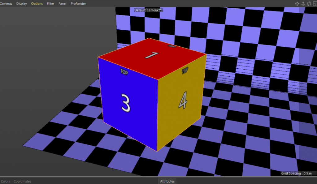
this will also be reflected in our 3D view and now we can see the colours and numbers perfectly mapped to each face of the cube.
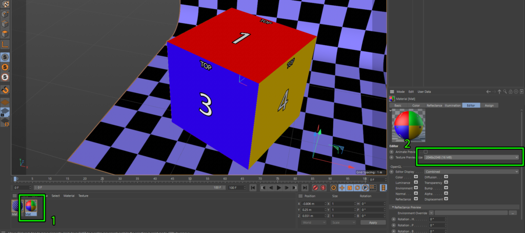
If we jump back into startup layout your texture might look like its displayed at low res on your cube and look really crunchy. To make things look sharper you need to increase the texture preview size. Do this by selecting your texture (1) and then change the texture preview size to something higher than it is from the drop down as shown below (2).
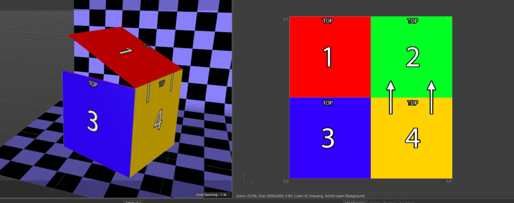
So all of that was pretty straight forward but I would like to change the UV layout, in the 2d workflow applying content to this cube i want it to flow up the left side and over the top essentially where the crease would be if we unfolded it. I modified the UV content template to show what I would like.
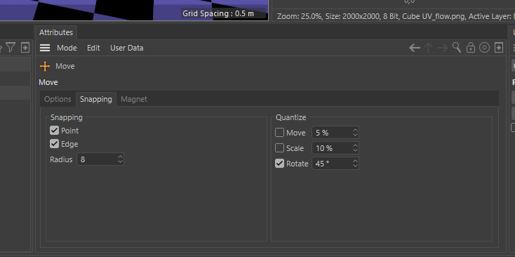
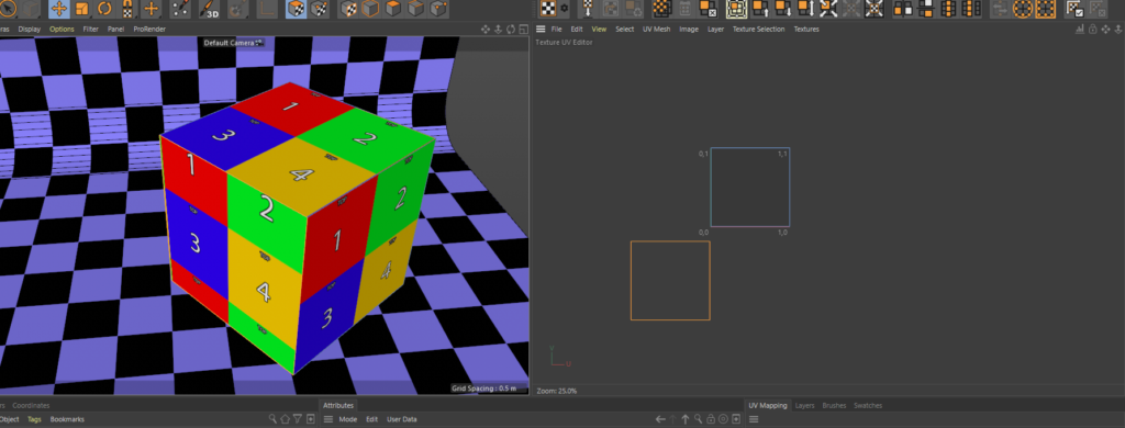
If we jump back into UV layout, it looks like we can just move that UV polygon to the right. First of all hit the E key to use the move tool and in the snapping tab bottom centre select Point and Edge for Snapping, also select rotate and set it to 45 degree. This will allow us to move the selection precisely, now select the top left UV polygon in the UV space and move it right so it snaps to the right quadrant.
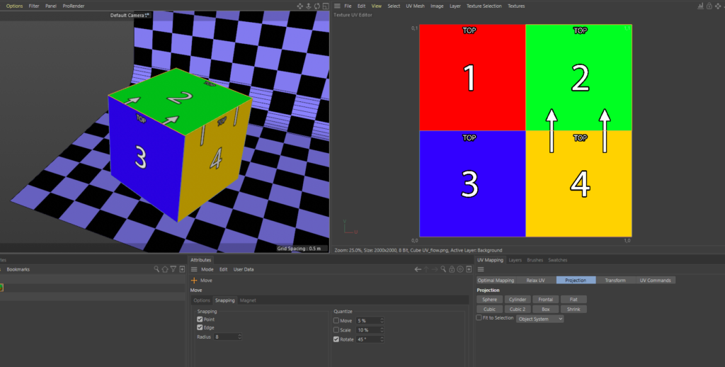
Now it hasn’t completely dine what was expect, we also need to rotate the UV anticlockwise. Because we have snapped the rotate to 45 degree increments we can just use the rotate tool.
Select the rotate tool by hitting the R Key, select click on the UV we want to rotate and drag left, do this twice until it is rotated. Now its exactly how i would like it, the snapping selections are really key here, of snap rotate is not selected and you rotate a UV a few times it can be difficult to get back to perpendicular.
Now lets move onto cube 2 and do this a little different, click on Cube 2 and then clear the UV canvas background if it doesn’t do it when you click on Cube 2 as shown below in the textures window. You can easily bring up the textures you’ve previously loaded here from this selection menu.
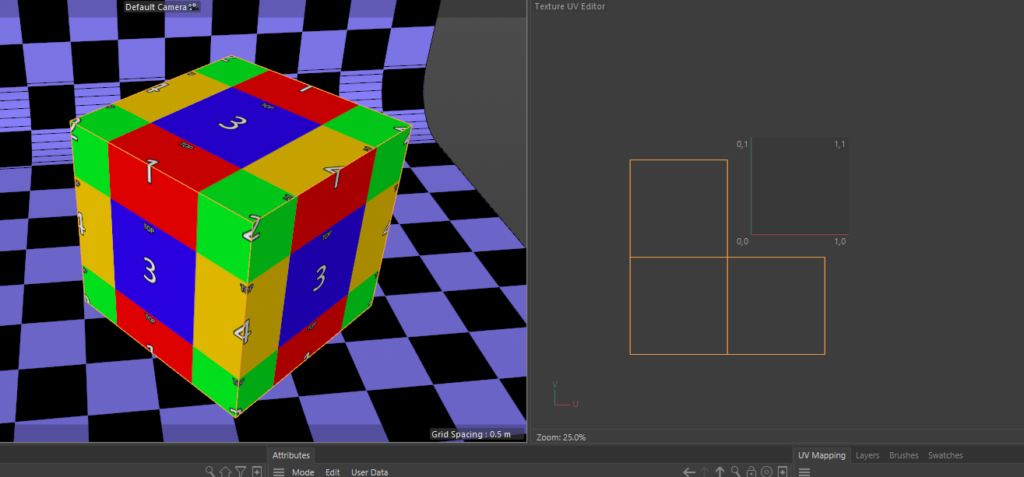
For this cube were gonna do this quick and dirty, we just want to select the bottom left face but we cant just grab that in the UV window as they are all stacked on-top of each other. Instead of clicking in the UV window, providing your UV polygon selection is turned on and you have the move tool selected you can just click that face in the 3D view and then go over to the UV space scroll zoom out and drag it around, you can see how it repeats the UV when outside of the UV space.
Now drag all the squares and arrange them like this, on this cube i want the content flow, or hinge to be between the 2 left faces. Were working a little blind here but can see with our previously created texture everything is rotated the right way.
To get this looking more sensible hit ctrl + a to select all the UV and then click on the Fit UV to canvas button like we did earlier, this will pull all the UV into the normalised UV space now the cube texture will look correct.
There we have it, there’s quite a few little steps here to remember and selections but hopefully will help anyone new to UV mapping in cinema wishing to build disguise projects.
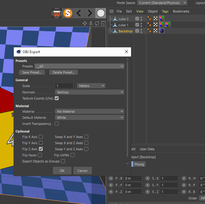
Now all we need to do is export our mesh into our disguise project mesh folder and now we have our really handy Export Selected Object As.. button we can export each of our mesh individually. Lets start by exporting the backdrop, select the Backdrop in the Objects window, then clock on the Export Selected Objects button and select wavefront OBJ from the bottom of the list. I made a preset for disguise and these are my settings.
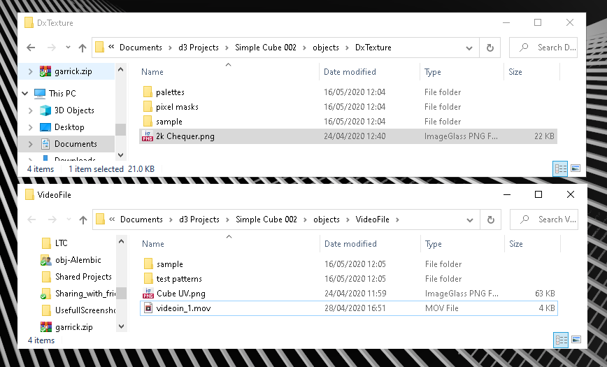
Once I’ve exported all the mesh i also put my texture into he project too i put the Cube UV texture into the video folder, but because I’m going to use the backdrop as a prop that needs to go into DxTexture folder so we can apply it to the prop.
After bringing all the mesh into disguise and direct mapping to the cubes we have a mirror of our cinema project. From here if any changes to the mesh are needed I do all the changes in cinema and re-export that element. This gives me much more control, accuracy and flexibility than moving and scaling in in disguise direct
I hope this has been helpful to anyone reading and if you have any questions please reach out to me. Next post will be about generating content templates and working with the content team.
Intro I’ve been meaning to do this for a long time, passing on my knowledge of my personal workflow for building video projects using the disguise media server and Cinema 4D. For anyone new to the blog, I’ve been using disguise (formally known as d3) heavily since 2014 and have built many big video projects over the past 6 years. Prior to this i was building my own media server applications using vvvv , quartz composer and other software since 2005.
Beginning There’s quite allot of knowledge to pass on here of various different techniques so I’m gonna start at the super basics of UV mapping a basic flat surface in C4D, these things come as default in the disguise software but this process will serve as a good basis for bigger more complex things which I promise you they will get complex.
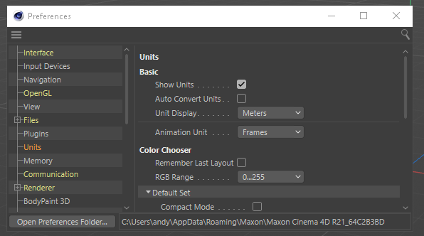
C4D Setup First thing is I set up my blank cinema project so it shares the same units and scaling as the disguise environment, hit CTRL+E to bring up a preferences windows and set the units to meters after selecting the Units options so all dimensions are displayed in meters
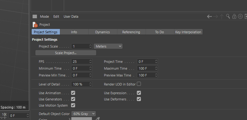
Next is to set the Project scale to meters CTRL+E which will display the “project settings” in the bottom left window. Set the project scale to 1 = Meters.
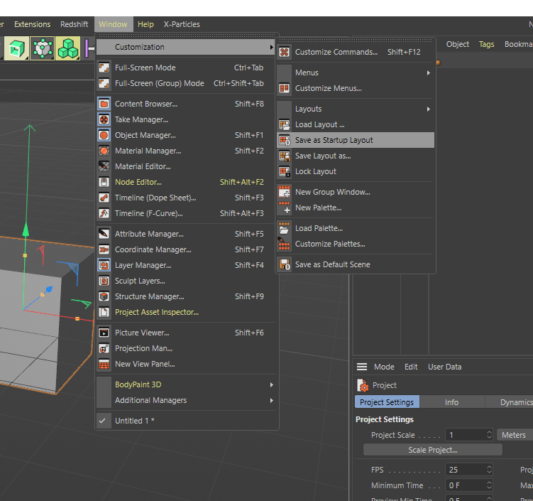
And, finally, to save these as the defaults for each time you open cinema. click on the Window menu, along to customisation and then hit save as default layout. This is really useful as if you find yourself using the same setup each time, this includes 3D objects in the scene and textures you can build what you use most commonly and save as startup layout.
That’s it, all done with the setup, now were ready to UV a flat surface. So far, I’ve been under the assumption that you know what a UV is. Just in case you don’t, here’s a very basic description.
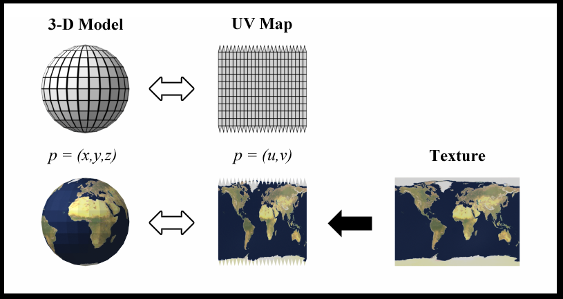
What is a UV To be able to apply an image texture to a 3d object it needs to have its pixel space defined, this is a way of relating a 2D flat image space to a 3D image space. In short its essentially origami in reverse….kind of. Below is an image taken from Wikipedia UV mapping which shows the UV and the relationship to how an earth image gets wrapped onto the 3D sphere and how a how a cube is unwrapped receptively.
Sphere and 2 d content exampleRepresentation of a cube UV unwrap
Making a basic screen in cinema Finally were here getting down to some nitty gritty of making something!! Now as default, when you create a basic basic object from the library in cinema it comes with a default UV space/tag. Sometimes we just want to draw a screen in 3D space using the polygon pen on-top of a received cad or something. These 3D objects created with the polygon pen don’t by default have a UV tag associated with them so I’m gonna show you how to add a UV tag.
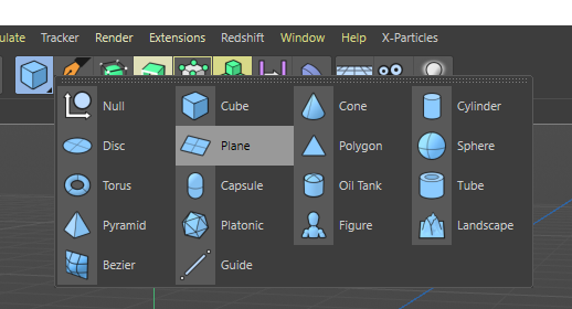
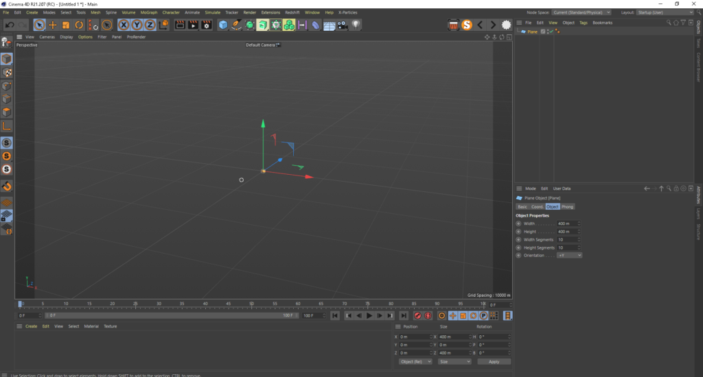
Lets start super basic first by making a plane, click and HOLD on the blue cube icon and then a menu and then it will open a menu to select a plane, move the mouse over that and release.
You now should now have a glorious flat plane in your 3D scene, and as of C4D_release21 you should see something like this. By default we’ve created a 400m x 400m flat plane divided into 10 sections by 10 sections. This is all good but we cant see anything useful in the d3 window and 400m square is far too big for what were trying to achieve.
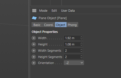
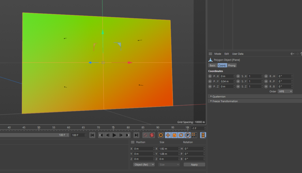
So, lets make this a more sensible size and the right place in our 3d view-port. Make sure the plane is selected in the content browser and set the object to the below settings, we are basically making a 1920 x 1080 pixel size screen (thus the width and height) and setting it the correct forward orientation split into 2×2 segments. The reason for splitting into segments is for further down the line if you have 2 projectors covering the surface and you need QuickCal points in the centre and the edges centre, I’ll cover QuckCal in detail in later posts.
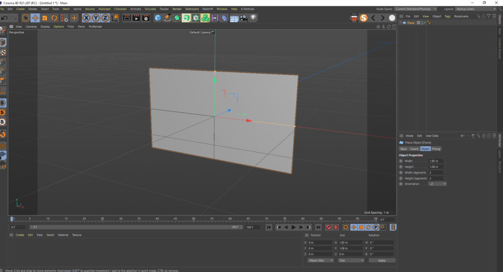
Now we have our simple plane in the 3d view, hit n-b on the keyboard which is the shortcut to display the object in Gouraud Shading with Lines mode. The object is still in object mode which means we can parametrically change, in this case the divisions on the fly. However we need the object to be editable and you can do this by making sire the object is selected and hitting C on the keyboard, the only way to get back to parametric mode is to undo so you need to be happy with your settings before you make it editable. I quite often save in versions so now would be a good time to hit save as “callmenames_v001” before hitting C and then save again as “callmesnames_v002”. Quick note here, for all the rest of this post, the orientation of the 3d view camera is at -Z to the mesh. +X is right +Y is Up and +Z is moving away from the camera.
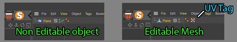
Once you hit that C key you will see the icon change from a plane inti a triangle which means this is now a mesh. You will also see a black and white chequer box appears and that is the UV tag, this is what defines the pixel space for our object, without this you wont be able to apply an image or a move to it as there s no map for which 2D pixel should go where on the 3D object. Lets delete this, just to show an example on how you add a UV tag if you’ve generated your mesh via another method, or maybe imported from something with no UV
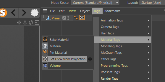
The easiest way to add a UV tag is make sure your mesh is selected, go to the tags menu, scroll down to the materials option and then click Set UVW from Projection this will add our tag back on but our UV map wont be correct, which is the perfect setup for the next step. Note: Earlier versions of C4D the location and the Set UV from Projection will be in a different place but easy enough to find looking though the menus
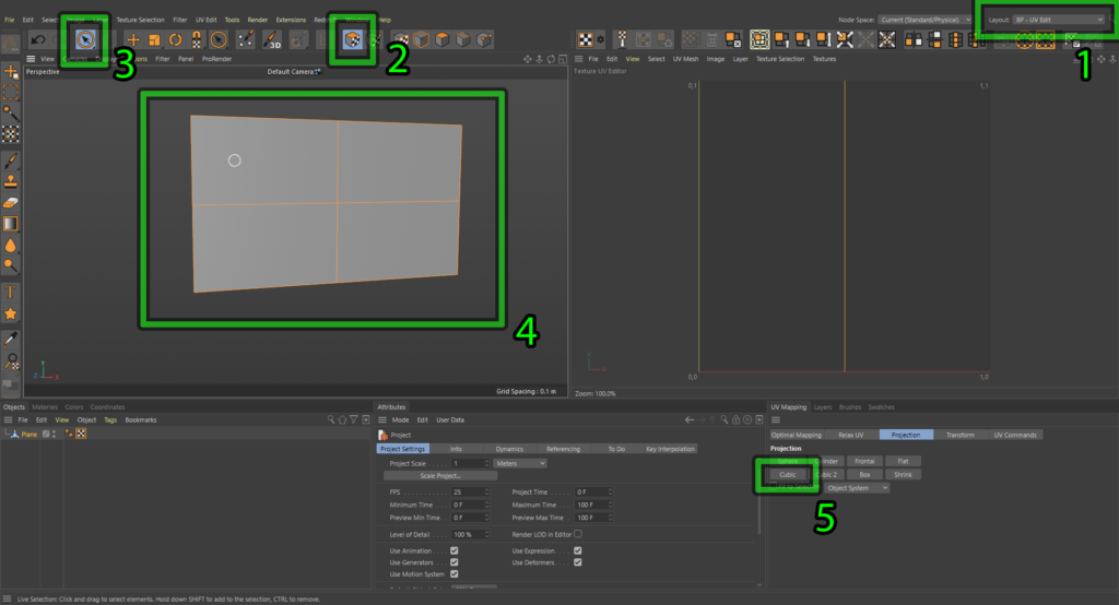
Next step in the process is to go into cinemas UV mapping layout, do this by selecting BP- UV Edit in the drop down (1). this will rearrange your work space and display the tools needed for UV editing, next…. (2) make sure the UV Polygons mode is engaged. (3) select your Live Selection tool. (4) make sure all the polygons are selected on your object. (5) and finally hit the cubic button. Once you hit that button, you will see in the UV texture editor window, change to 4 squares winch represent the UV pace of the 4 quadrants that make up the 3D object. Now is a pretty good time to click the other buttons in the UV mapping widow and see what happens but make sure you back on Cubic at the end.
R21 Layout
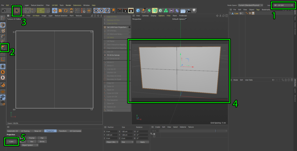
At the time of writing this Maxon updated their UV tools and completely rearranged the UV layout space. Here’s a screenshot to reflect those changes if your having trouble finding them. Also the Materials window is now below the 3D view port which you will need to know for the next part if your running R22
R22 Layout
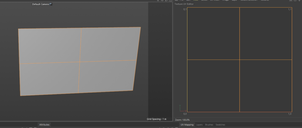
Now you should see something like below but we need to make sure none of our UV squares are flipped or rotated which can happen quite often when your dealing with multiple screens. Next step ill show you my method for checking this super quickly in cinema
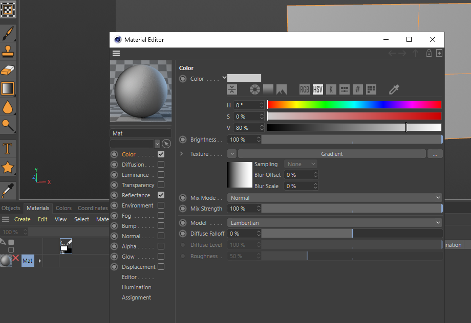
Select the materials tab and then create new default material and then double clock the material to bring up the material editor window. Make sure colour is selected and then in the texture drop down arrow select gradient, this will give us a default gradient of black to white horizontally.
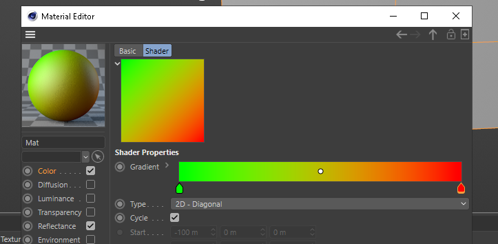
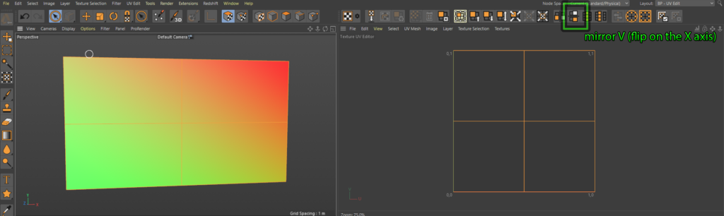
We want the gradient to be diagonal and my preferences are a green to red gradient, to do this double click the gradient square window, which will bring up another widow and copy my settings below. you change the colours by double clicking on the gradient tags below the horizontal bar. Once your done, close the window and now we have the ultimate orientation checking tool.
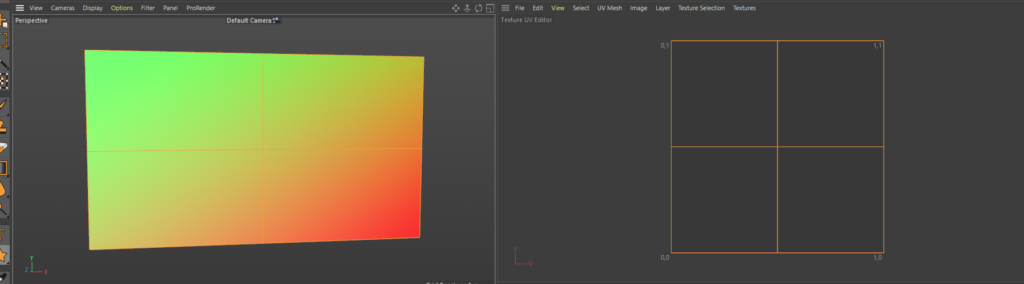
Drag your new texture on your model and if everything is in the correct origination you will always see green top left and red bottom right. if this isn’t the case then something is flipped in the X or Y
Correct UV orienation
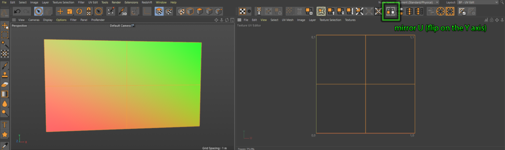
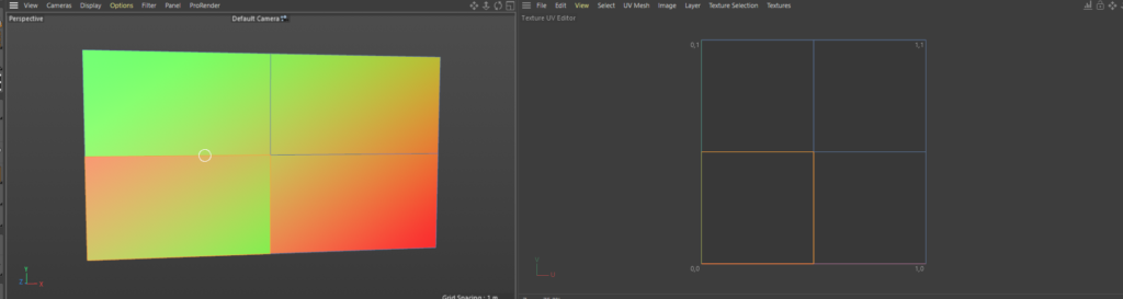
Below are a couple of examples of if the UV is flipped, make sure the whole object is still selected and UV Polygon mode. if you click these buttons highlighted you can see the effects of the flipping and orientation
UV flipped on the Y axisUV Flipped on the X axis
And then to get even more detailed you can even select individual, polygons and flip them move them do whatever you like with them and really mess up your UV texture space. This is a great example of how the diagonal gradient can quickly help identify incorrect flips.
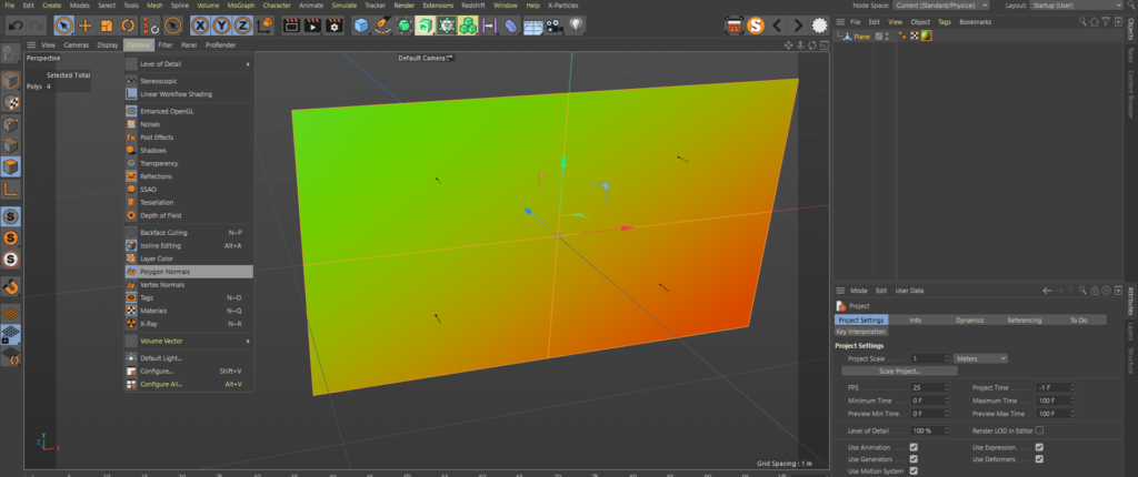
I’m not gonna cover all the buttons and tools here in this post, this will become more in depth on the next one which we will unwrap a cube. Now that we have our mesh UV’d and everything is orientated correctly we need to check our polygon normal’s. Basically the normal’s are which is the front and which is the back of the polygon, this is really important for disguise as it uses this information when calculating various things. For example, if your normal’s are facing away from the projector then dynamic soft edge will not work correctly.
To make sure the normal’s are facing the correct way, jump back into your “Startup (User)” layout. Make sure your in polygon selection mode and select all the polygons in the scene, then in the options tab shown below, and turn on Polygon normals. Now you will see some tiny arrows in the view port showing which s the front face of the polygon and we can see everything is facing the correct way. If you do need to change the orientation the shortcut is to hit U then R and you will see the arrows flip to the other side.
So now we have our mesh which is the size we want, our UV’s are correct and our normals are facing the correct way. I’m gonna move the mesh up so that it sits at 0,0,0 in world space at its bottom centre. I basically moved it up in the Y half the height of the mesh. This means when we bring it into disguise it will sit right on 0,0,0 too.
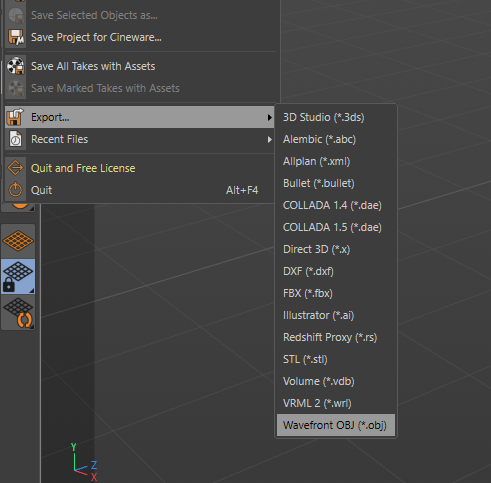
OK lets export this thing into disguise! Currently cinemas inbuilt export tools are pretty crap and I’ll get onto the other options for exporting in future posts. For this occasion we will use the standard export option. TO access this go to the file tab, scroll down to Export then select Wavefront OBJ at the bottom of the list.
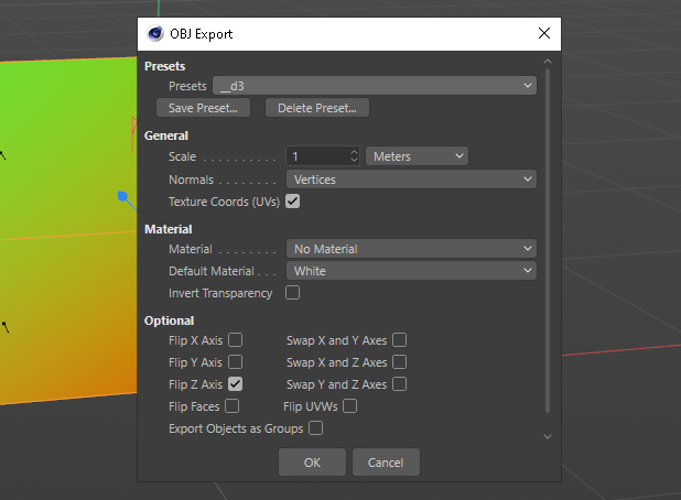
This will bring up a dialog box, like below, I’ve created a preset for disguise and these are export settings you should use ad you can export straight into the disguise mesh folder and save it as whatever you wish.
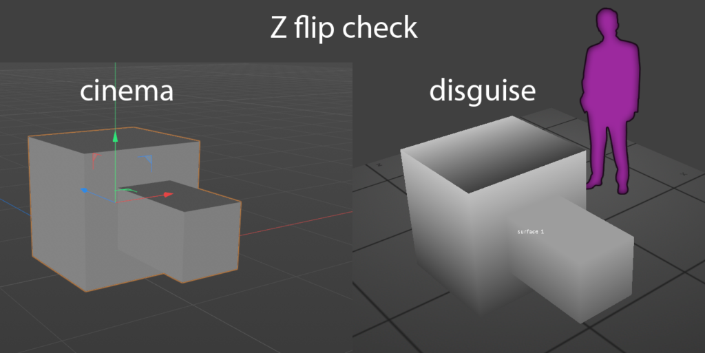
Big Note: One of the most useful things you can do to make your life easier in the long term is understand the import and export characteristics between the various software’s. knowing what needs the Z flipping and how the default scaling factor is between different things. Below is a simple shape shape I export to check z-flips between software, the small nubbin is always facing Z- and it would be really clear when importing into disguise if the z does or doesn’t need flipping as the nubbin would be facing Z+, the wrong way.
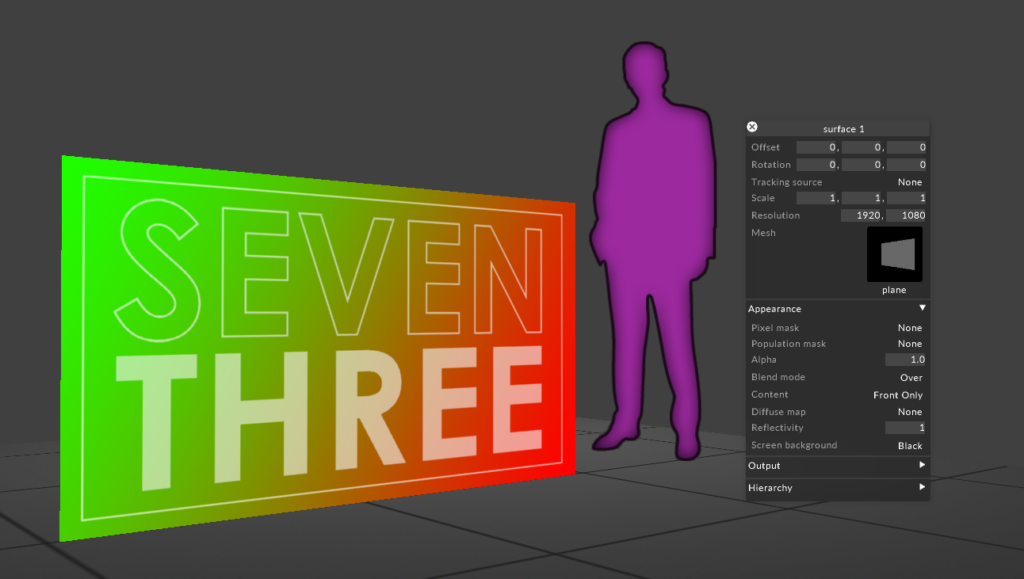
And here we are finally our generated plane from cinema exported and imported into disguise. I’m going to assume you understand the basics of how to import the mesh and bring it into disguise. All scaling, position and orientation is correct and i double checked this by generating a little test pattern, basically my favourite UV checker gradient and some text,
Closing That’s it I hope I’ve manged to pass on some knowledge, I appreciate that these are super baby steps. And with this example, quite allot of steps to quite a boring result but I promise you, following this workflow and the techniques will make building projects in cinema and bringing them it to disguise will start to become quicker and easier. Next post coming soon, unwrapping a cube in cinema, generating a content template and more cinema UV detailed tool explanations.
Please leave any comments, suggestions and questions below and thanks for reading, best Andy