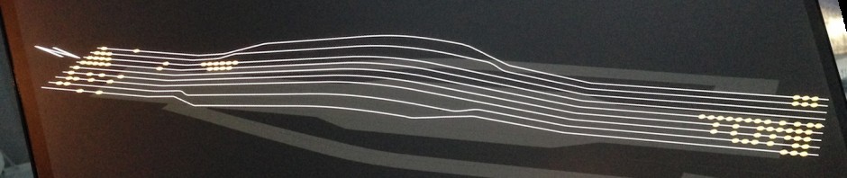
Hello everyone, following on from the previous blog post I’m going to be running through building from scratch the above disguise project and reasons behind the methods. Im going to be continuing this series in Cinema4D R21, I found a bug in R22 which breaks my workflow, I’ve spoke with Maxon and waiting fro them to fix it. The cinema project and relating assets for this post can be downloaded here: 002 C4D-d3_workflows
I’m primarily going to be concentrating on the 3D project build up here and less on the disguise side of things as there’s some excellent training resources out there already. I highly recommend you check out my good friend and colleague Rich Porters YouTube channel for disguise tips and tricks.

Lets get started by adding a really useful button to your cinema workspace and this is so we can export objects as separate elements. Using the export option in the file menu only allows us to export everything in the scene as one object and we want separate elements. Adding this button will allow you to export selected objects individually.
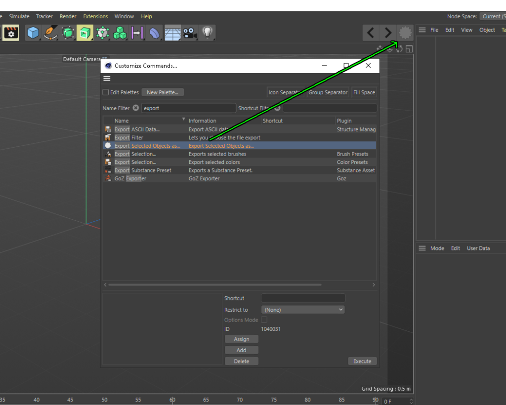
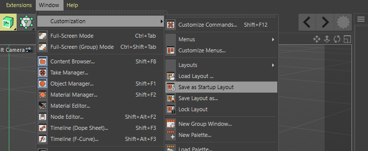
Fist of all hit Shift + F12 to bring up the customise commands menu ins in the search bar type “export” and this will narrow down a list of export commands. We want Export Selected Object as..click on this and drag it on to the tool bar. Once you’ve done that, save as startup layout as show before so the button stays there on restart. Its currently greyed out and that’s because we don’t have an object selected or any objects in our scene.
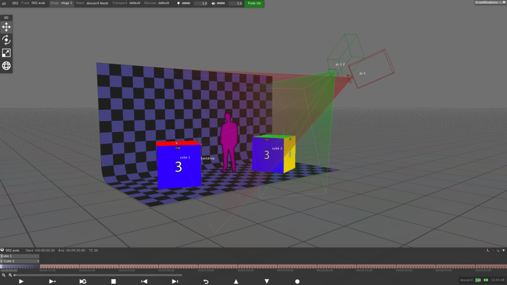
What the audience can see
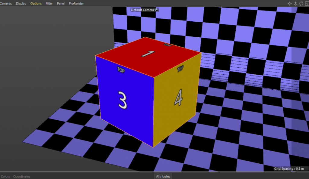
So the scenario is that e have a small stage and 2 cubes onstage which are projecting onto, the audience are in front of the stage theatre style and can see the forward facing parts of the cubes and the tops. This is always my starting question when speaking with the creative team in the early stage. In this case, in our 3d scene we only need the parts of the object which are going to be seen by the audience and we can focus on making the best use of the UV space, theirs no point in wasting good UV space on a part of the object which isn’t going to be projected on. I always like to have the venue stage in my scene as its a really good reference eve if its not going to be projected onto, and it makes things look nice. Make a stage like below, 6m wide 3m deep and 3m high, easiest way to do this is make a cube to those dimensions and delete all but the bottom and rear face, I then positioned the downstage centre of my stage to 0,0,0 in my scene. If you want to skip this part use the backdrop.obj from the assets download above.
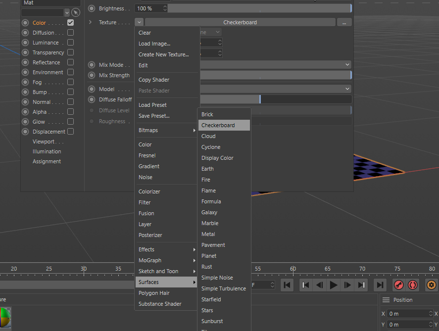
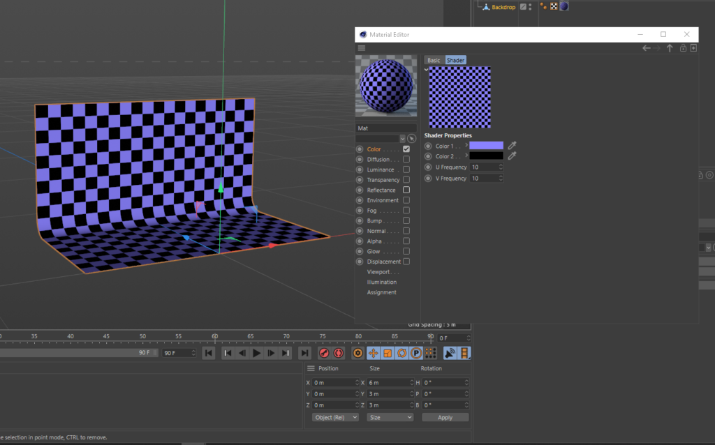
I then created a new material and selected the checker board from the surfaces menu in the materials options and then double click on the thumbnail to bring up another window and set the colours and amount of squares to your taste.
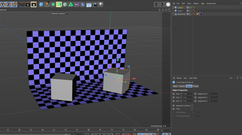
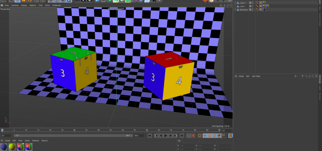
Now we have our stage setup lets make a couple of cubes, we could make one and duplicate it but making 2 is good practice and each will have a slightly different associated UV. Next create 2 cubes and make them both 1 meter x 1 meter x 1 meter and place them in your scene like below, make them editable by selecting them and hitting C on the keyboard.
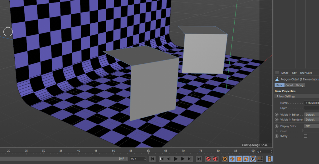
now all we need here is the front faces of the cube, only the faces which the audience will see and the projectors are hitting. The quickest way to do this is make sure your in polygon selection mode, select the faces you want then hit the keys U then I then delete. This will invert the selection and delete the rear faces which we don’t need, your scene should look like the image below.
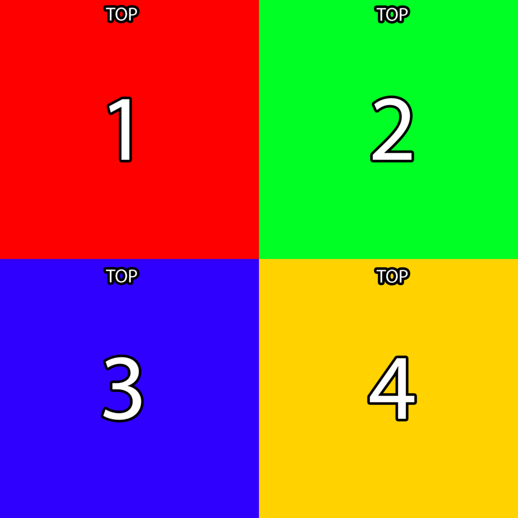
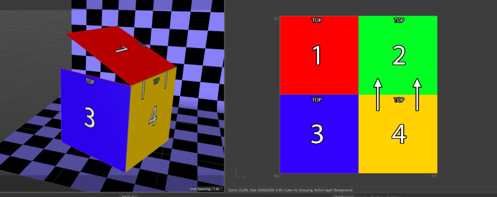
Now we have put two cubes and know the dimensions, from here we can make life infinitely easier for ourselves by creating a simple guide for ourselves to unwrap to. we know each face is the same size so I made a simple 2×2 colour grid with numbers and text to say which way is up.
Net pull that image onto your cubes in cinema and jump into UV layout.
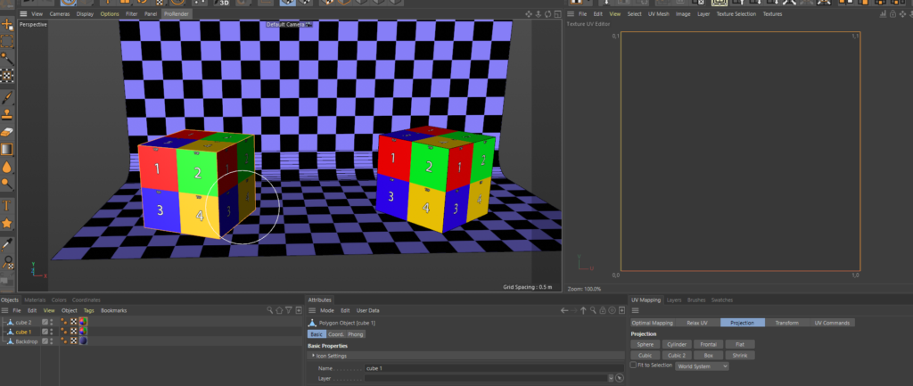
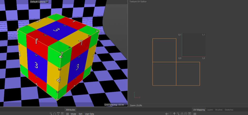
NOTE: I found a bug in R22 with the fit to canvas command so ill be showing this in R21 and again update this to show the R22 method once Maxon fix the bug. Yous shoud now see the same as below, our helpful lineup grid is replicated on all three faces on each cube this is the default UV map when you create a cube in Cinema, were gonna change this so each face only sees one of the colour quadrants.
R21 UV instructions
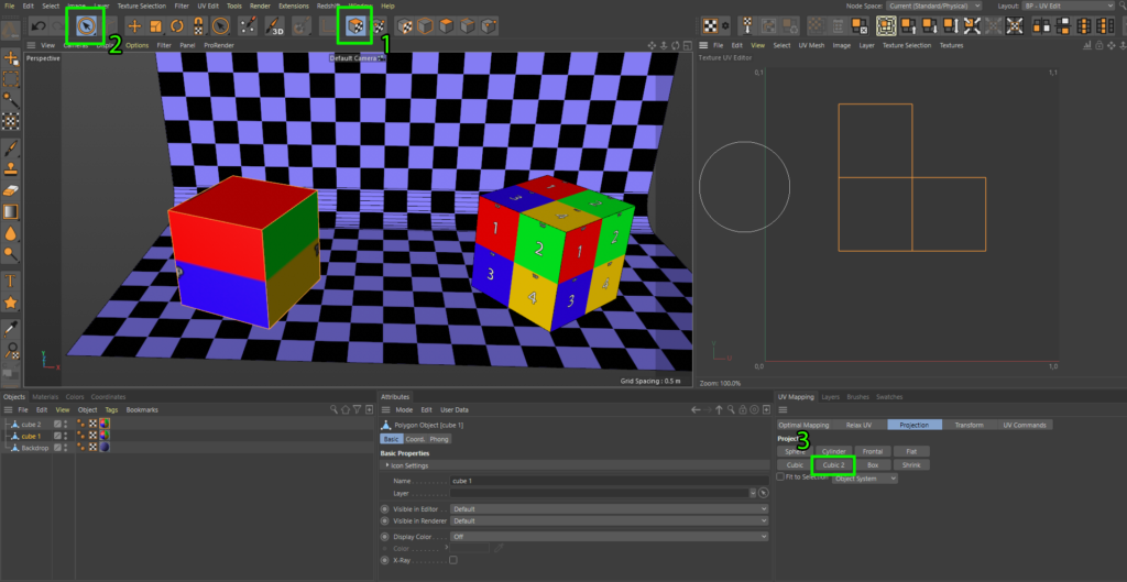
Using the screenshot as guide below, make sure your in UV polygon selection mode (1) , then choose the section tool (2) and select all the faces on cube 1 then hit the Cubic 2 button (3) and you should see the scene like this, make sure the drop-down below the Cubic 2 button is set to object system for this to work. This has automatically unwrapped each face of the cube for us, but its still not right, we want the selection to fill the UV space.
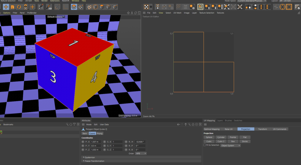
To make things visually easier lets load our Cube UV image we created earlier into the UV space window and then click the fit UV to canvas button (1). This will expand our selection to fill the UV space
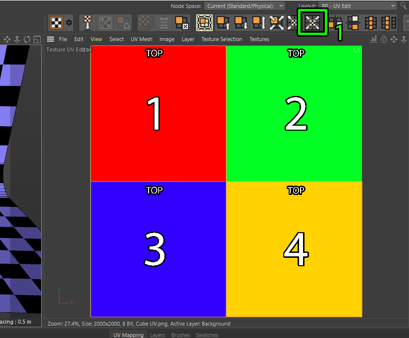
this will also be reflected in our 3D view and now we can see the colours and numbers perfectly mapped to each face of the cube.
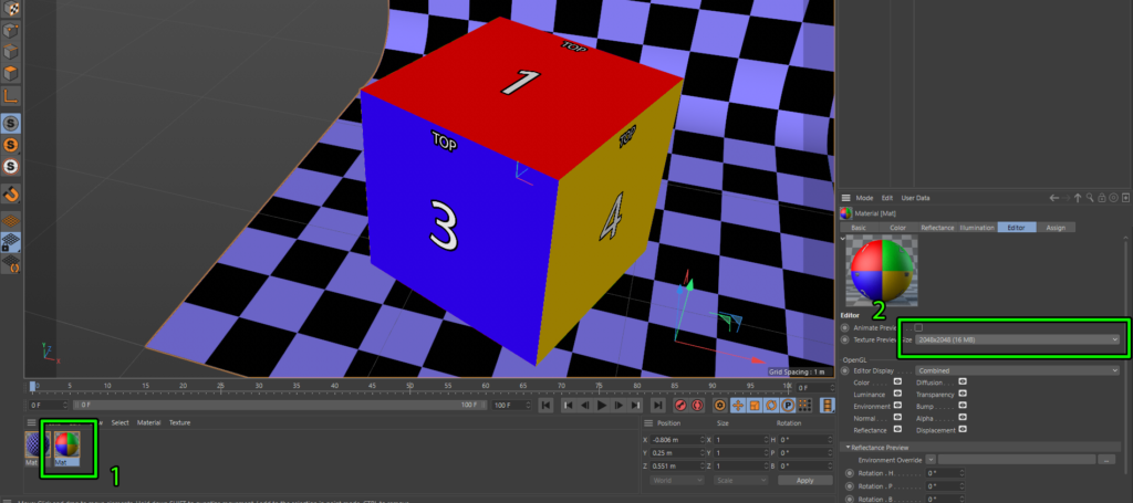
If we jump back into startup layout your texture might look like its displayed at low res on your cube and look really crunchy. To make things look sharper you need to increase the texture preview size. Do this by selecting your texture (1) and then change the texture preview size to something higher than it is from the drop down as shown below (2).
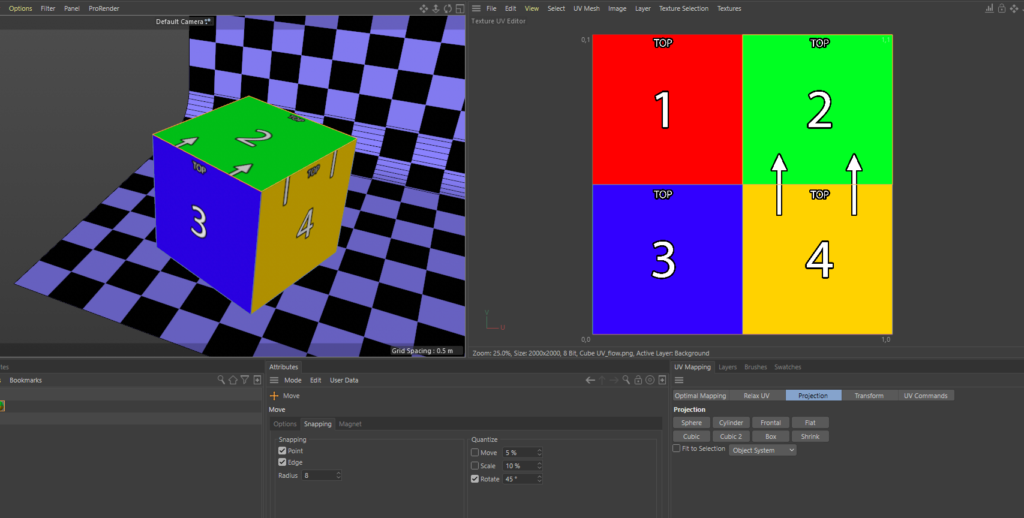
So all of that was pretty straight forward but I would like to change the UV layout, in the 2d workflow applying content to this cube i want it to flow up the left side and over the top essentially where the crease would be if we unfolded it. I modified the UV content template to show what I would like.
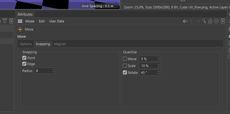
If we jump back into UV layout, it looks like we can just move that UV polygon to the right. First of all hit the E key to use the move tool and in the snapping tab bottom centre select Point and Edge for Snapping, also select rotate and set it to 45 degree. This will allow us to move the selection precisely, now select the top left UV polygon in the UV space and move it right so it snaps to the right quadrant.
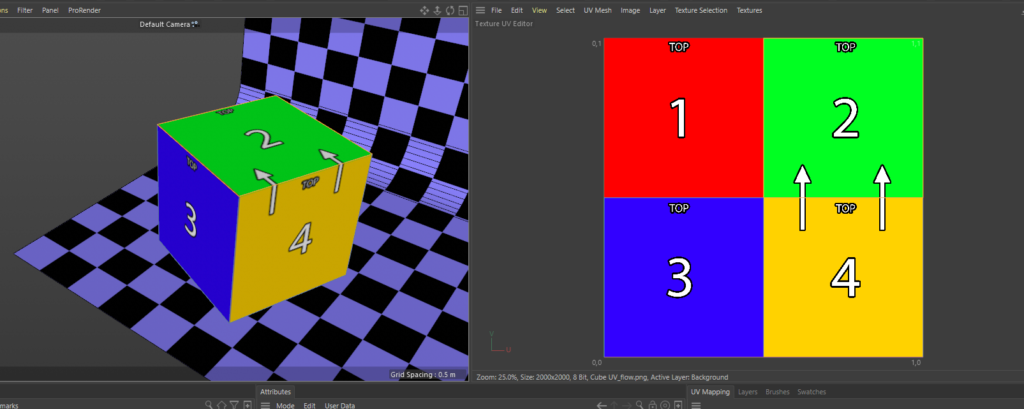
Now it hasn’t completely dine what was expect, we also need to rotate the UV anticlockwise. Because we have snapped the rotate to 45 degree increments we can just use the rotate tool.
Select the rotate tool by hitting the R Key, select click on the UV we want to rotate and drag left, do this twice until it is rotated. Now its exactly how i would like it, the snapping selections are really key here, of snap rotate is not selected and you rotate a UV a few times it can be difficult to get back to perpendicular.
Now lets move onto cube 2 and do this a little different, click on Cube 2 and then clear the UV canvas background if it doesn’t do it when you click on Cube 2 as shown below in the textures window. You can easily bring up the textures you’ve previously loaded here from this selection menu.
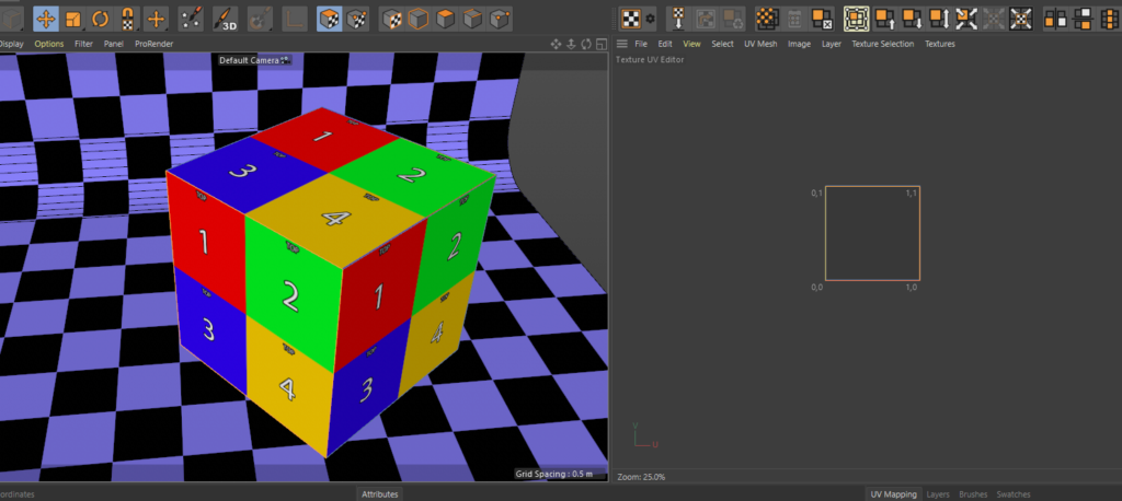
For this cube were gonna do this quick and dirty, we just want to select the bottom left face but we cant just grab that in the UV window as they are all stacked on-top of each other. Instead of clicking in the UV window, providing your UV polygon selection is turned on and you have the move tool selected you can just click that face in the 3D view and then go over to the UV space scroll zoom out and drag it around, you can see how it repeats the UV when outside of the UV space.
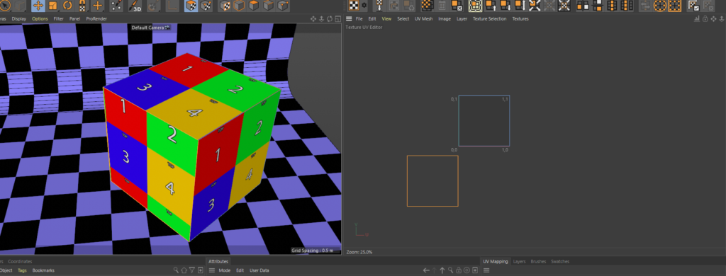
Now drag all the squares and arrange them like this, on this cube i want the content flow, or hinge to be between the 2 left faces. Were working a little blind here but can see with our previously created texture everything is rotated the right way.
To get this looking more sensible hit ctrl + a to select all the UV and then click on the Fit UV to canvas button like we did earlier, this will pull all the UV into the normalised UV space now the cube texture will look correct.
There we have it, there’s quite a few little steps here to remember and selections but hopefully will help anyone new to UV mapping in cinema wishing to build disguise projects.
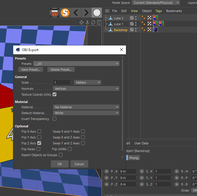
Now all we need to do is export our mesh into our disguise project mesh folder and now we have our really handy Export Selected Object As.. button we can export each of our mesh individually. Lets start by exporting the backdrop, select the Backdrop in the Objects window, then clock on the Export Selected Objects button and select wavefront OBJ from the bottom of the list. I made a preset for disguise and these are my settings.
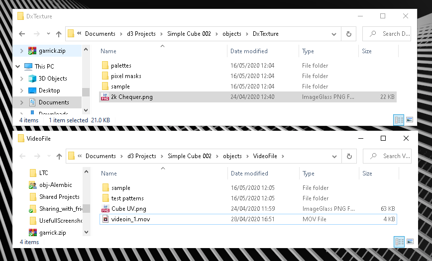
Once I’ve exported all the mesh i also put my texture into he project too i put the Cube UV texture into the video folder, but because I’m going to use the backdrop as a prop that needs to go into DxTexture folder so we can apply it to the prop.
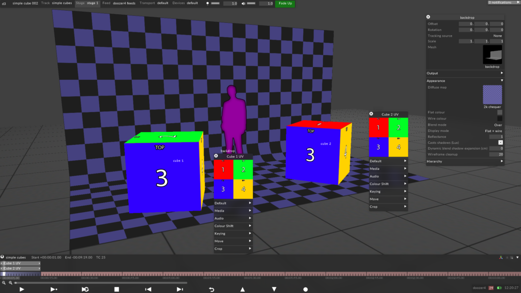
After bringing all the mesh into disguise and direct mapping to the cubes we have a mirror of our cinema project. From here if any changes to the mesh are needed I do all the changes in cinema and re-export that element. This gives me much more control, accuracy and flexibility than moving and scaling in in disguise direct
I hope this has been helpful to anyone reading and if you have any questions please reach out to me. Next post will be about generating content templates and working with the content team.
Thanks Andy never thought about only doing that the audiace sees could you do the full cube but only UV the faces you need or is it better to just not have the faces?
Hey Jack, any faces which aren’t going to be projected on or don’t have content I ditch. On the odd occasion where a piece of geometry isn’t going to receive content but is covered by projection and would be useful to have those edges for lineup I add them is a seperate UV’d mesh of that makes sense ?.
Hi Andy, im very thankfull for your workflows between c4d and disguise, im just stuck on one part, i looked on your blog but without success.
So i can bake textures out and apply them to an obj in disguise thats all relative easy, but how do you bake a more complex c4d animation to an uv based texture sequence ?
Imagine i have a cube in real life, and i recreate this cube in a mograph cloner to have the clones move on an axis based on a noise shader, how do i export this animation for the uv map ? Tradionally i would have sourced where the projectors would come , their lens specs and render the projector perspectives, but im trying to understand how do this with UV’s for cases where i dont know where the projectors will come. Hope im a bit understandable here.
Thanks !