Projection study pitch for Hawthorn 2018
Intro
I’ve been meaning to do this for a long time, passing on my knowledge of my personal workflow for building video projects using the disguise media server and Cinema 4D. For anyone new to the blog, I’ve been using disguise (formally known as d3) heavily since 2014 and have built many big video projects over the past 6 years. Prior to this i was building my own media server applications using vvvv , quartz composer and other software since 2005.
Beginning
There’s quite allot of knowledge to pass on here of various different techniques so I’m gonna start at the super basics of UV mapping a basic flat surface in C4D, these things come as default in the disguise software but this process will serve as a good basis for bigger more complex things which I promise you they will get complex.
C4D Setup
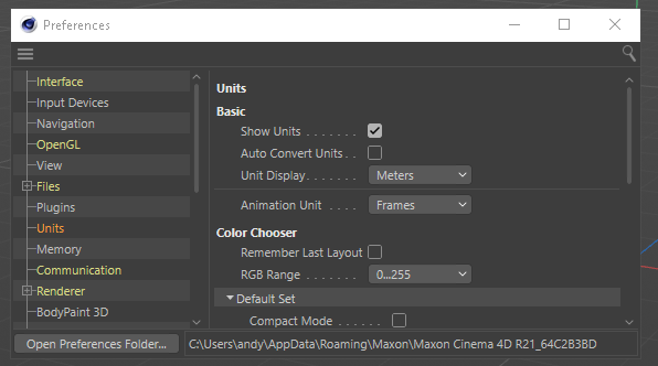
First thing is I set up my blank cinema project so it shares the same units and scaling as the disguise environment, hit CTRL+E to bring up a preferences windows and set the units to meters after selecting the Units options so all dimensions are displayed in meters
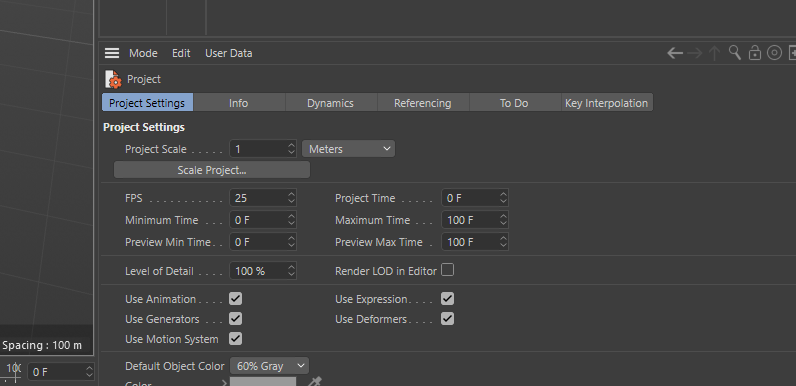
Next is to set the Project scale to meters CTRL+E which will display the “project settings” in the bottom left window. Set the project scale to 1 = Meters.
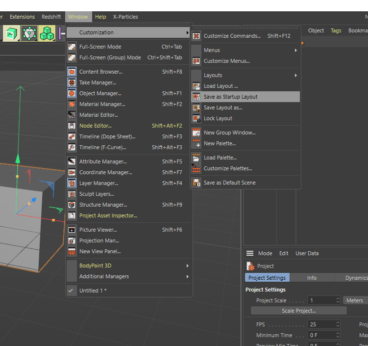
And, finally, to save these as the defaults for each time you open cinema. click on the Window menu, along to customisation and then hit save as default layout. This is really useful as if you find yourself using the same setup each time, this includes 3D objects in the scene and textures you can build what you use most commonly and save as startup layout.
That’s it, all done with the setup, now were ready to UV a flat surface. So far, I’ve been under the assumption that you know what a UV is. Just in case you don’t, here’s a very basic description.
What is a UV
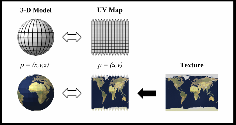
To be able to apply an image texture to a 3d object it needs to have its pixel space defined, this is a way of relating a 2D flat image space to a 3D image space. In short its essentially origami in reverse….kind of. Below is an image taken from Wikipedia UV mapping which shows the UV and the relationship to how an earth image gets wrapped onto the 3D sphere and how a how a cube is unwrapped receptively.
Making a basic screen in cinema
Finally were here getting down to some nitty gritty of making something!! Now as default, when you create a basic basic object from the library in cinema it comes with a default UV space/tag. Sometimes we just want to draw a screen in 3D space using the polygon pen on-top of a received cad or something. These 3D objects created with the polygon pen don’t by default have a UV tag associated with them so I’m gonna show you how to add a UV tag.
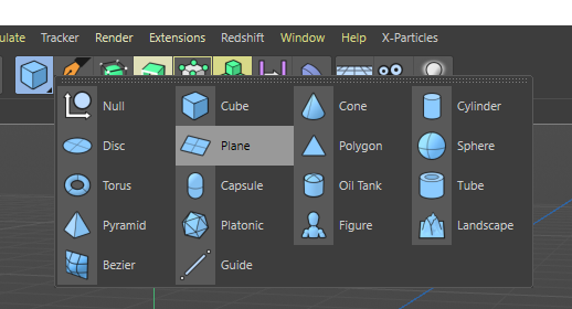
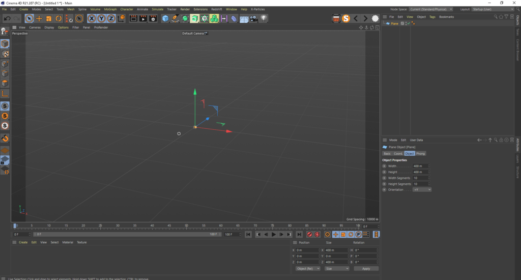
Lets start super basic first by making a plane, click and HOLD on the blue cube icon and then a menu and then it will open a menu to select a plane, move the mouse over that and release.
You now should now have a glorious flat plane in your 3D scene, and as of C4D_release21 you should see something like this. By default we’ve created a 400m x 400m flat plane divided into 10 sections by 10 sections. This is all good but we cant see anything useful in the d3 window and 400m square is far too big for what were trying to achieve.
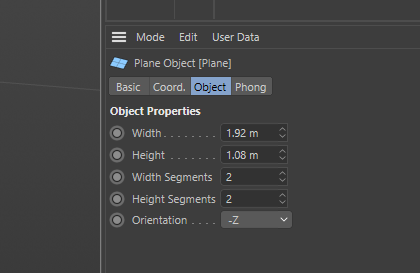
So, lets make this a more sensible size and the right place in our 3d view-port. Make sure the plane is selected in the content browser and set the object to the below settings, we are basically making a 1920 x 1080 pixel size screen (thus the width and height) and setting it the correct forward orientation split into 2×2 segments.
The reason for splitting into segments is for further down the line if you have 2 projectors covering the surface and you need QuickCal points in the centre and the edges centre, I’ll cover QuckCal in detail in later posts.
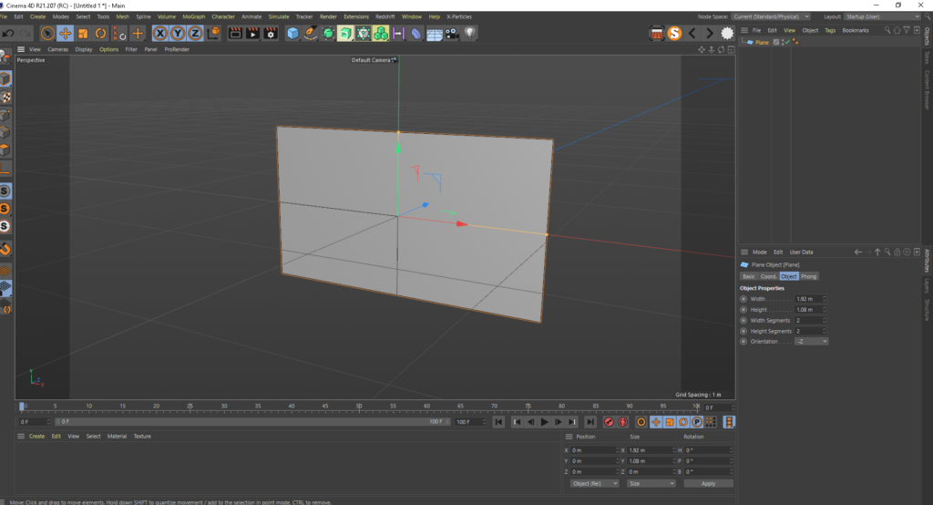
Now we have our simple plane in the 3d view, hit n-b on the keyboard which is the shortcut to display the object in Gouraud Shading with Lines mode. The object is still in object mode which means we can parametrically change, in this case the divisions on the fly. However we need the object to be editable and you can do this by making sire the object is selected and hitting C on the keyboard, the only way to get back to parametric mode is to undo so you need to be happy with your settings before you make it editable. I quite often save in versions so now would be a good time to hit save as
“callmenames_v001” before hitting C and then save again as “callmesnames_v002”.
Quick note here, for all the rest of this post, the orientation of the 3d view camera is at -Z to the mesh. +X is right +Y is Up and +Z is moving away from the camera.
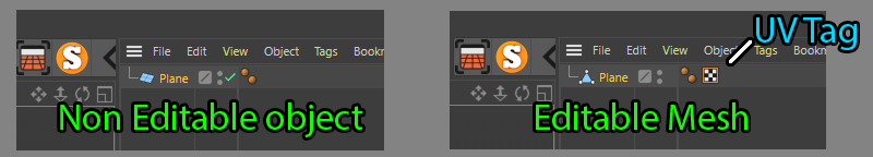
Once you hit that C key you will see the icon change from a plane inti a triangle which means this is now a mesh. You will also see a black and white chequer box appears and that is the UV tag, this is what defines the pixel space for our object, without this you wont be able to apply an image or a move to it as there s no map for which 2D pixel should go where on the 3D object.
Lets delete this, just to show an example on how you add a UV tag if you’ve generated your mesh via another method, or maybe imported from something with no UV
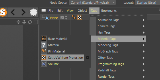
The easiest way to add a UV tag is make sure your mesh is selected, go to the tags menu, scroll down to the materials option and then click Set UVW from Projection this will add our tag back on but our UV map wont be correct, which is the perfect setup for the next step.
Note: Earlier versions of C4D the location and the Set UV from Projection will be in a different place but easy enough to find looking though the menus
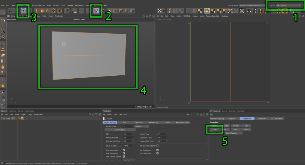
Next step in the process is to go into cinemas UV mapping layout, do this by selecting BP- UV Edit in the drop down (1). this will rearrange your work space and display the tools needed for UV editing, next….
(2) make sure the UV Polygons mode is engaged.
(3) select your Live Selection tool.
(4) make sure all the polygons are selected on your object.
(5) and finally hit the cubic button.
Once you hit that button, you will see in the UV texture editor window, change to 4 squares winch represent the UV pace of the 4 quadrants that make up the 3D object. Now is a pretty good time to click the other buttons in the UV mapping widow and see what happens but make sure you back on Cubic at the end.
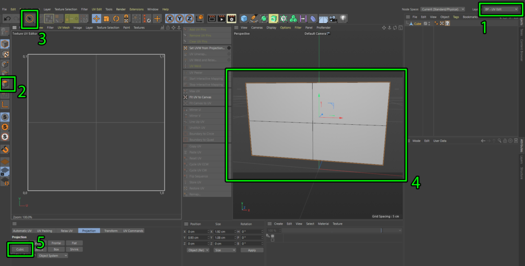
At the time of writing this Maxon updated their UV tools and completely rearranged the UV layout space. Here’s a screenshot to reflect those changes if your having trouble finding them. Also the Materials window is now below the 3D view port which you will need to know for the next part if your running R22
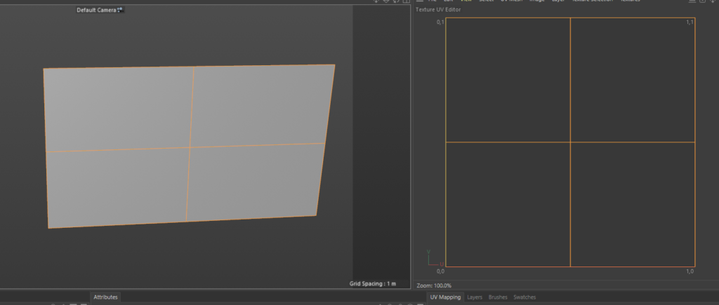
Now you should see something like below but we need to make sure none of our UV squares are flipped or rotated which can happen quite often when your dealing with multiple screens. Next step ill show you my method for checking this super quickly in cinema
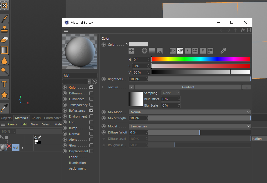
Select the materials tab and then create new default material and then double clock the material to bring up the material editor window. Make sure colour is selected and then in the texture drop down arrow select gradient, this will give us a default gradient of black to white horizontally.
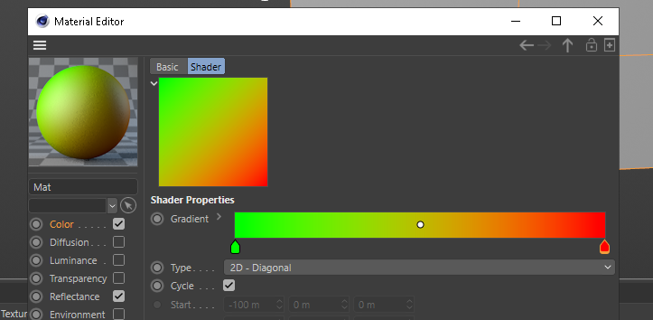
We want the gradient to be diagonal and my preferences are a green to red gradient, to do this double click the gradient square window, which will bring up another widow and copy my settings below. you change the colours by double clicking on the gradient tags below the horizontal bar. Once your done, close the window and now we have the ultimate orientation checking tool.
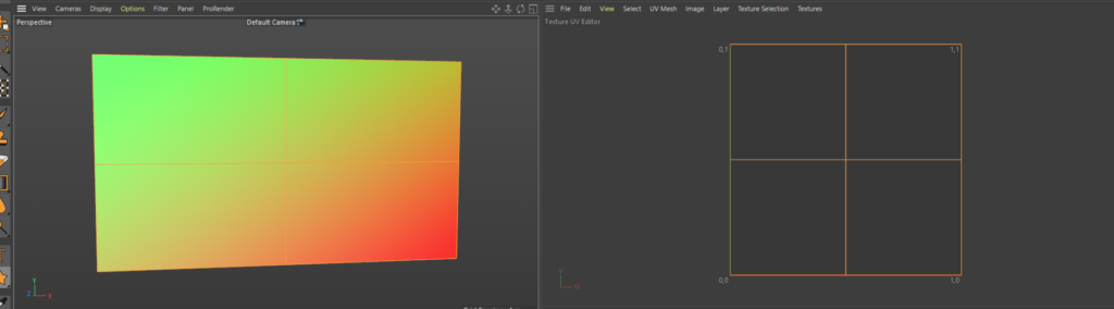
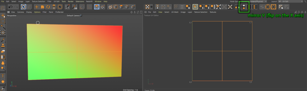
Drag your new texture on your model and if everything is in the correct origination you will always see green top left and red bottom right. if this isn’t the case then something is flipped in the X or Y
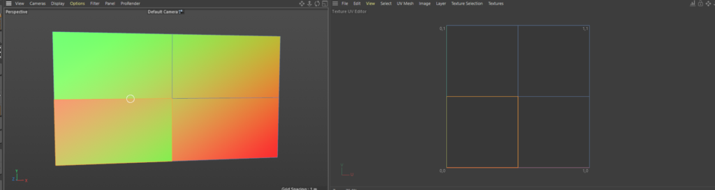
Below are a couple of examples of if the UV is flipped, make sure the whole object is still selected and UV Polygon mode. if you click these buttons highlighted you can see the effects of the flipping and orientation
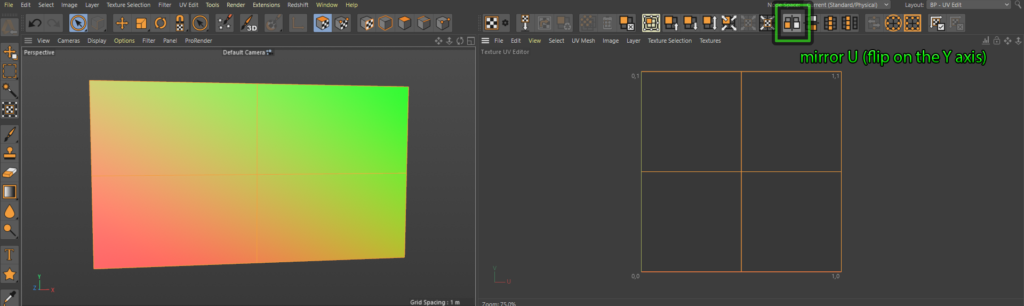
And then to get even more detailed you can even select individual, polygons and flip them move them do whatever you like with them and really mess up your UV texture space. This is a great example of how the diagonal gradient can quickly help identify incorrect flips.
I’m not gonna cover all the buttons and tools here in this post, this will become more in depth on the next one which we will unwrap a cube. Now that we have our mesh UV’d and everything is orientated correctly we need to check our polygon normal’s. Basically the normal’s are which is the front and which is the back of the polygon, this is really important for disguise as it uses this information when calculating various things. For example, if your normal’s are facing away from the projector then dynamic soft edge will not work correctly.
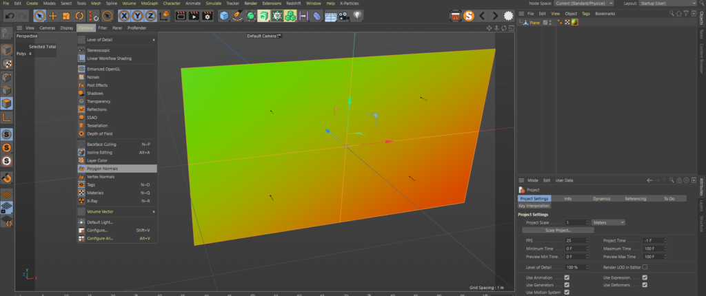
To make sure the normal’s are facing the correct way, jump back into your “Startup (User)” layout. Make sure your in polygon selection mode and select all the polygons in the scene, then in the options tab shown below, and turn on Polygon normals. Now you will see some tiny arrows in the view port showing which s the front face of the polygon and we can see everything is facing the correct way. If you do need to change the orientation the shortcut is to hit U then R and you will see the arrows flip to the other side.
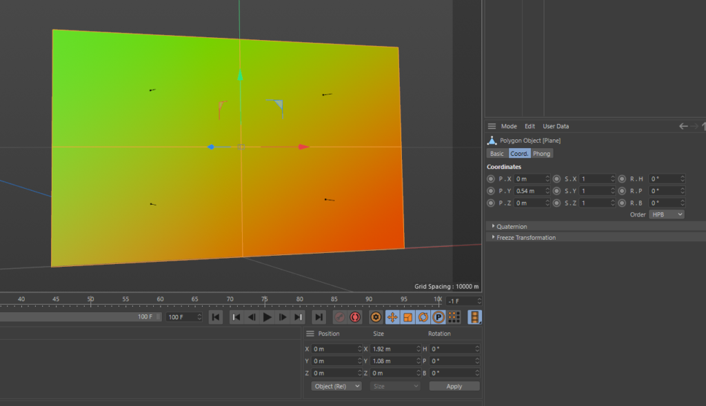
So now we have our mesh which is the size we want, our UV’s are correct and our normals are facing the correct way. I’m gonna move the mesh up so that it sits at 0,0,0 in world space at its bottom centre. I basically moved it up in the Y half the height of the mesh. This means when we bring it into disguise it will sit right on 0,0,0 too.
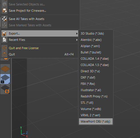
OK lets export this thing into disguise! Currently cinemas inbuilt export tools are pretty crap and I’ll get onto the other options for exporting in future posts. For this occasion we will use the standard export option. TO access this go to the file tab, scroll down to Export then select Wavefront OBJ at the bottom of the list.
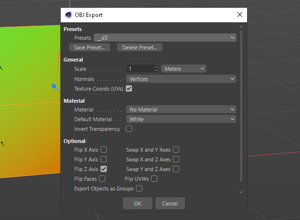
This will bring up a dialog box, like below, I’ve created a preset for disguise and these are export settings you should use ad you can export straight into the disguise mesh folder and save it as whatever you wish.
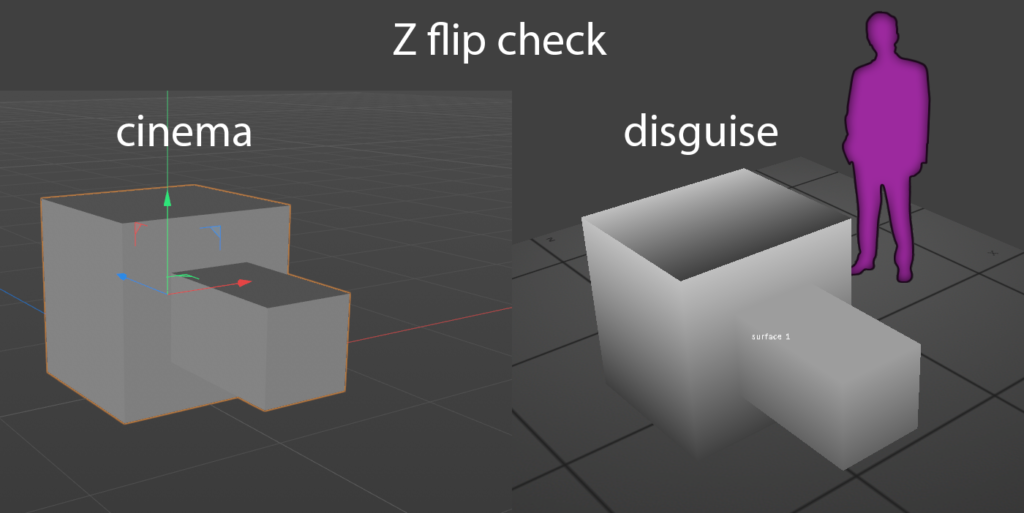
Big Note: One of the most useful things you can do to make your life easier in the long term is understand the import and export characteristics between the various software’s. knowing what needs the Z flipping and how the default scaling factor is between different things.
Below is a simple shape shape I export to check z-flips between software, the small nubbin is always facing Z- and it would be really clear when importing into disguise if the z does or doesn’t need flipping as the nubbin would be facing Z+, the wrong way.
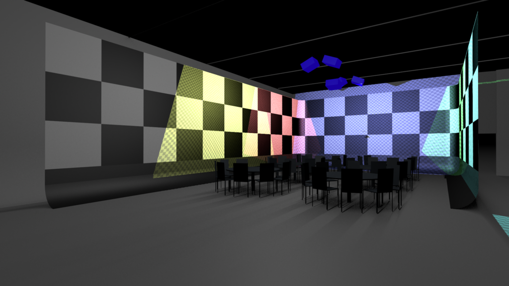
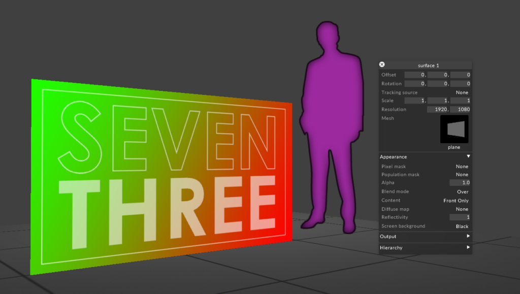
And here we are finally our generated plane from cinema exported and imported into disguise. I’m going to assume you understand the basics of how to import the mesh and bring it into disguise. All scaling, position and orientation is correct and i double checked this by generating a little test pattern, basically my favourite UV checker gradient and some text,
Closing
That’s it I hope I’ve manged to pass on some knowledge, I appreciate that these are super baby steps. And with this example, quite allot of steps to quite a boring result but I promise you, following this workflow and the techniques will make building projects in cinema and bringing them it to disguise will start to become quicker and easier.
Next post coming soon, unwrapping a cube in cinema, generating a content template and more cinema UV detailed tool explanations.
Please leave any comments, suggestions and questions below and thanks for reading, best Andy
Hey Andy, Thank you for posting these tutorials, they’re a huge help. Has the UV fit to canvas bug been fixed since the writing of this post? If so, what version should I look out for with C4D? I currently have S22. Thanks!
Hi Danny, just seen this!
I think it should be fixed in the latest version but I’ve not checked this, I’m still on old school r21 🙂
Hope your well!
Andy