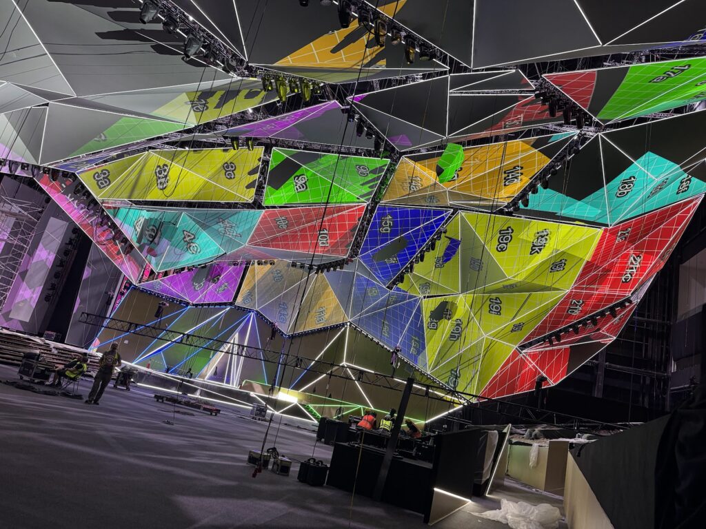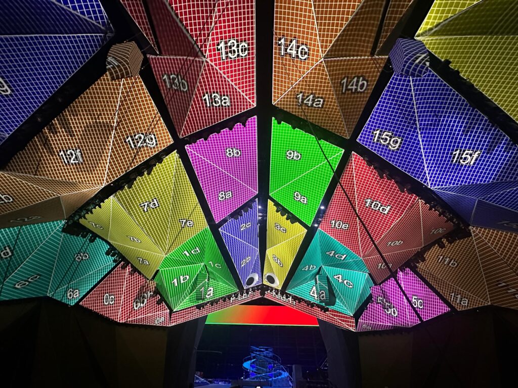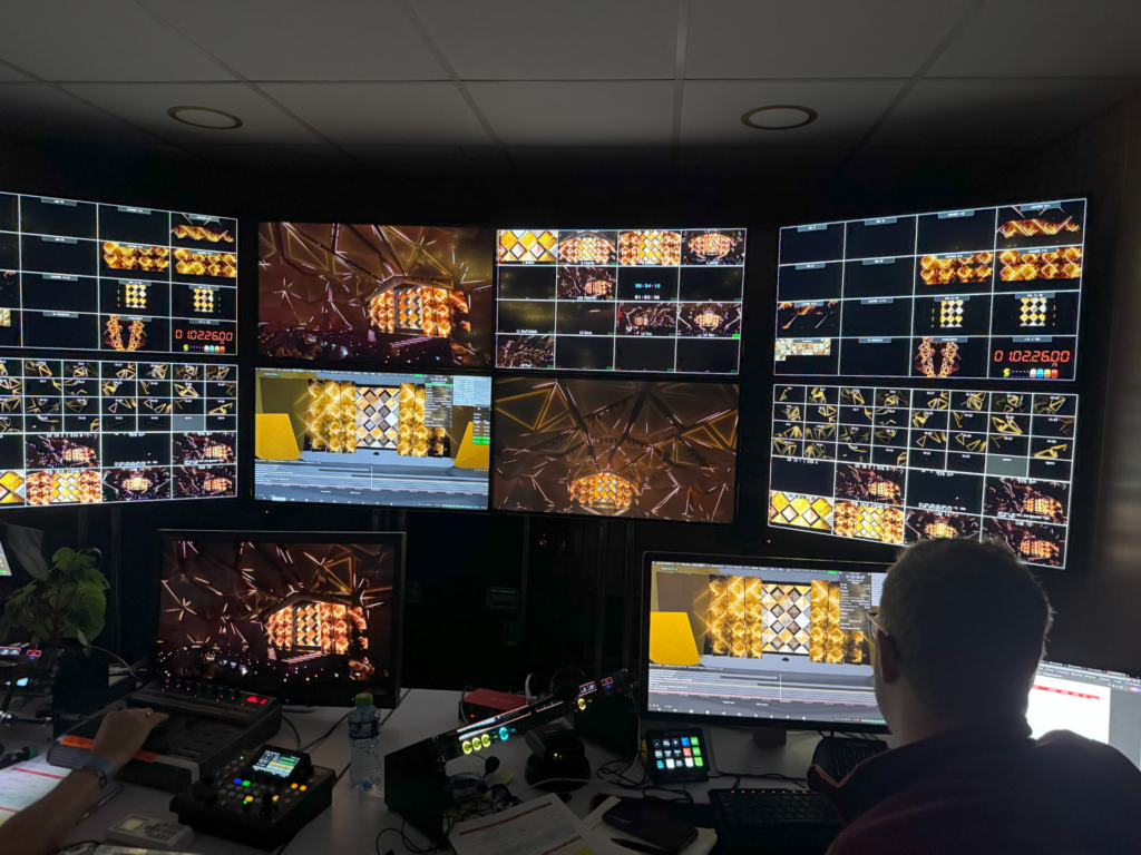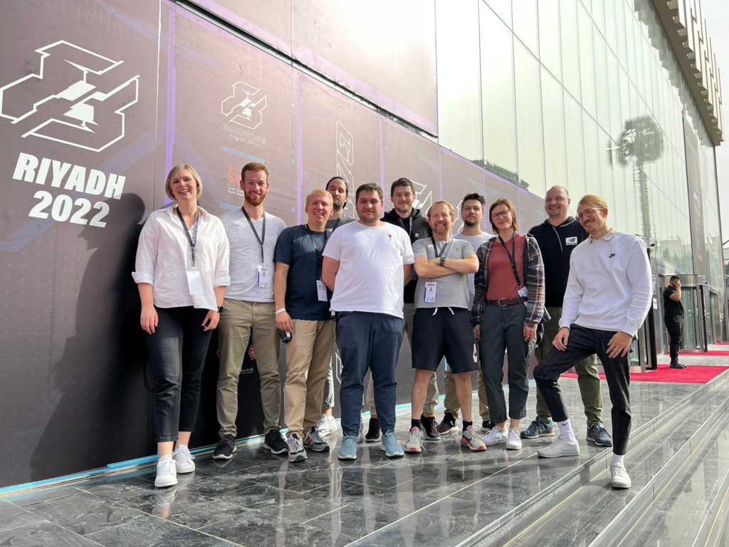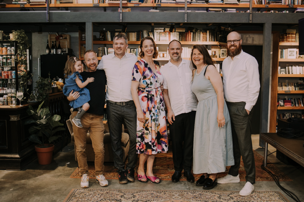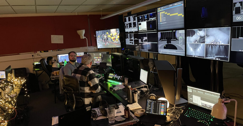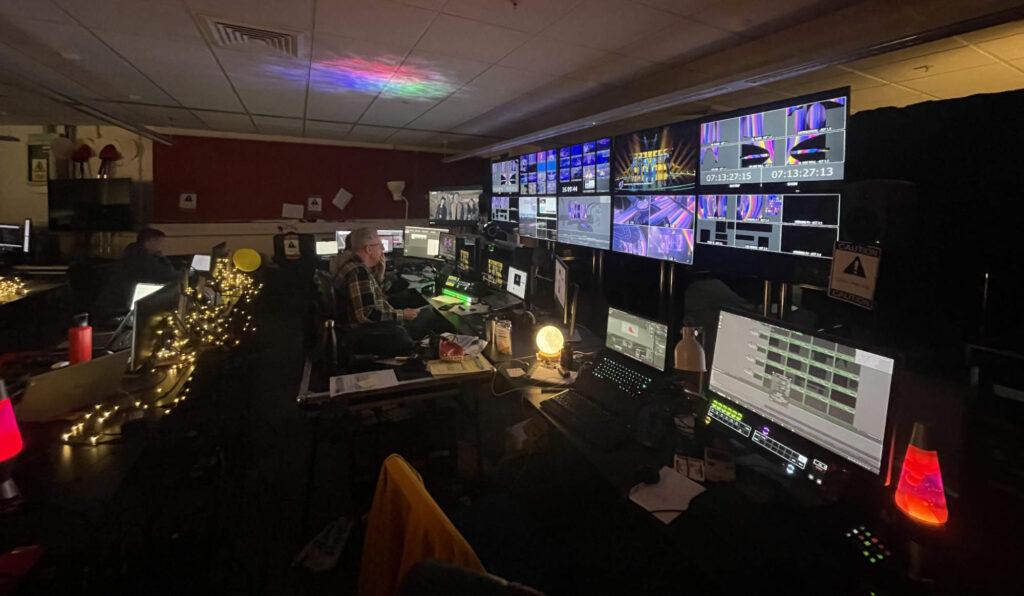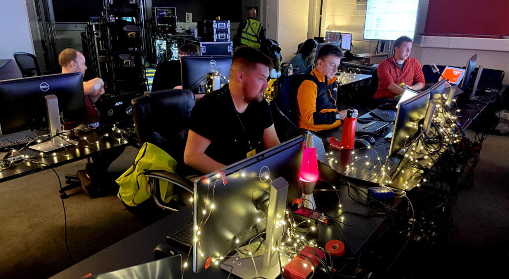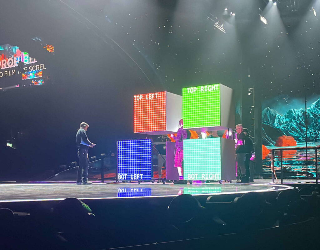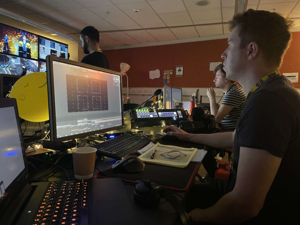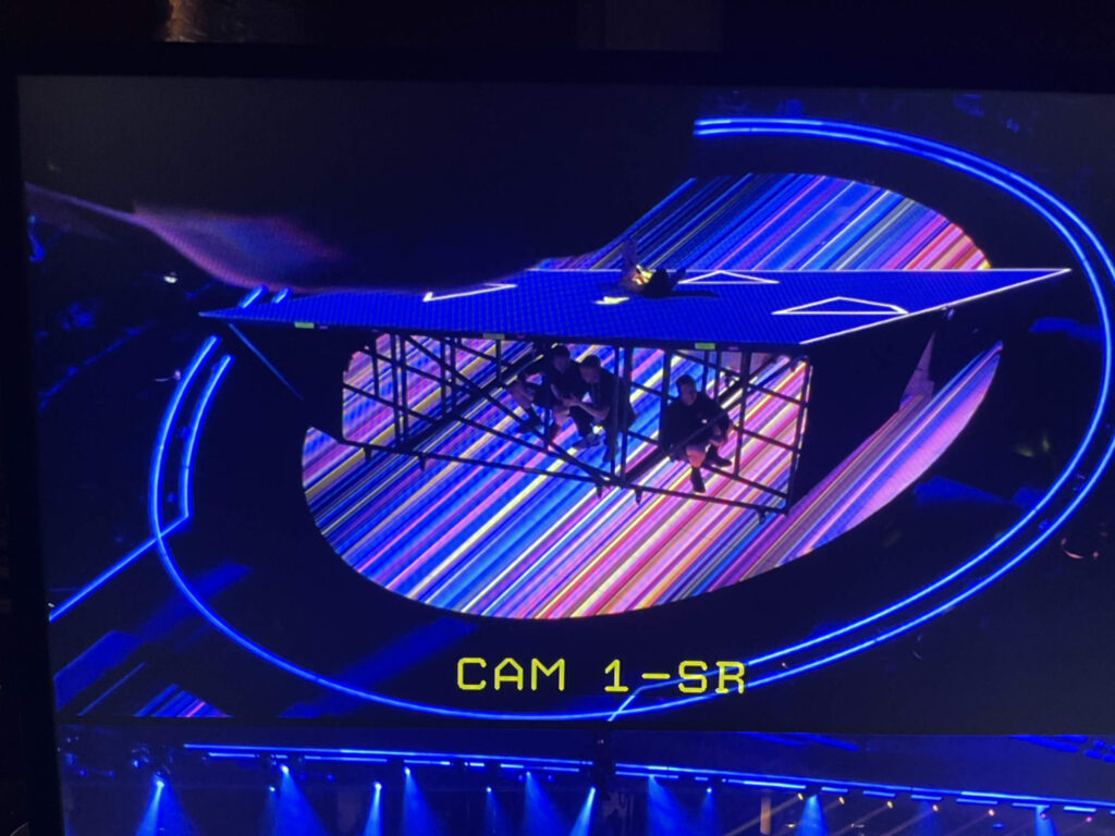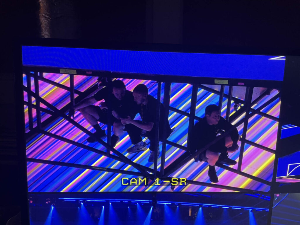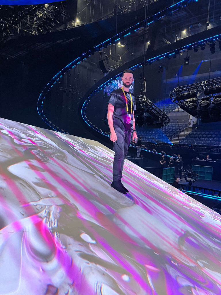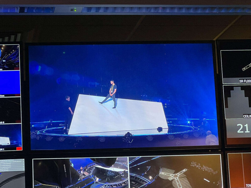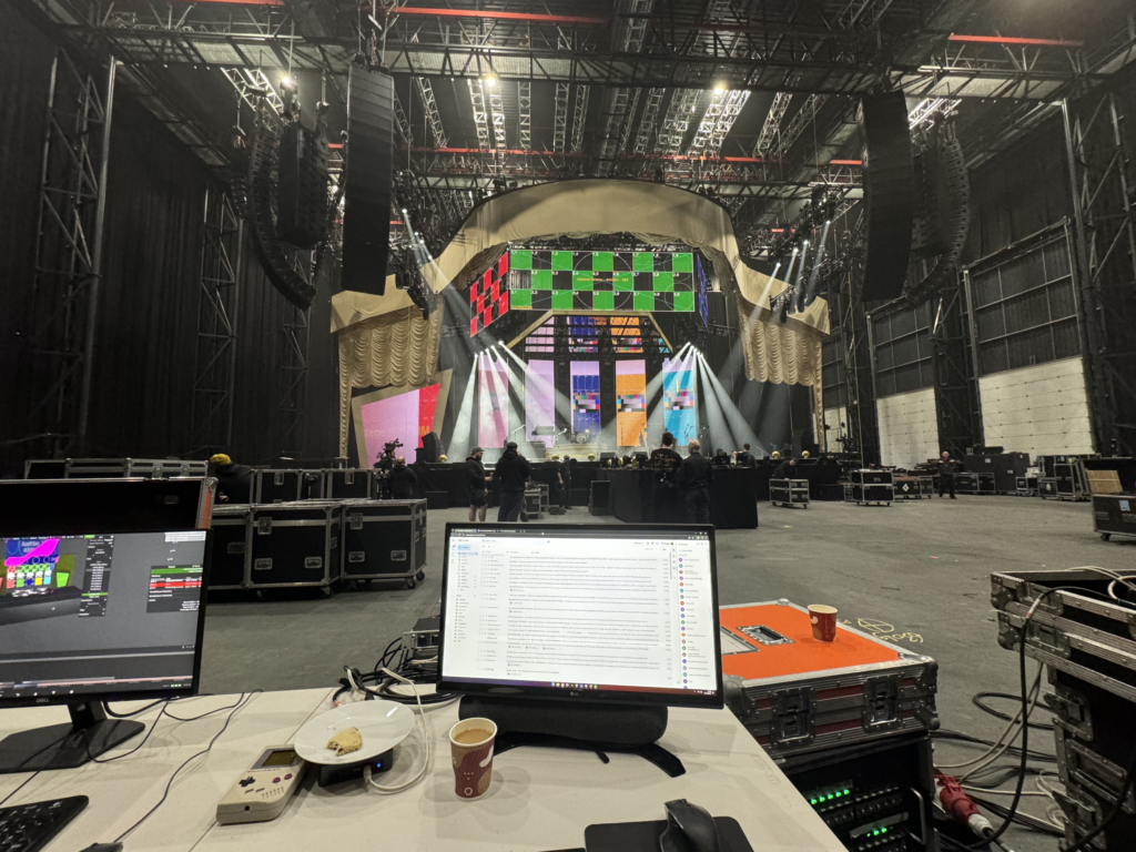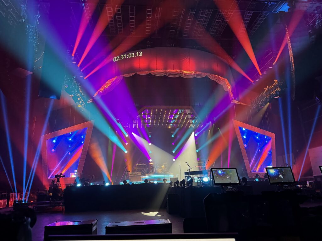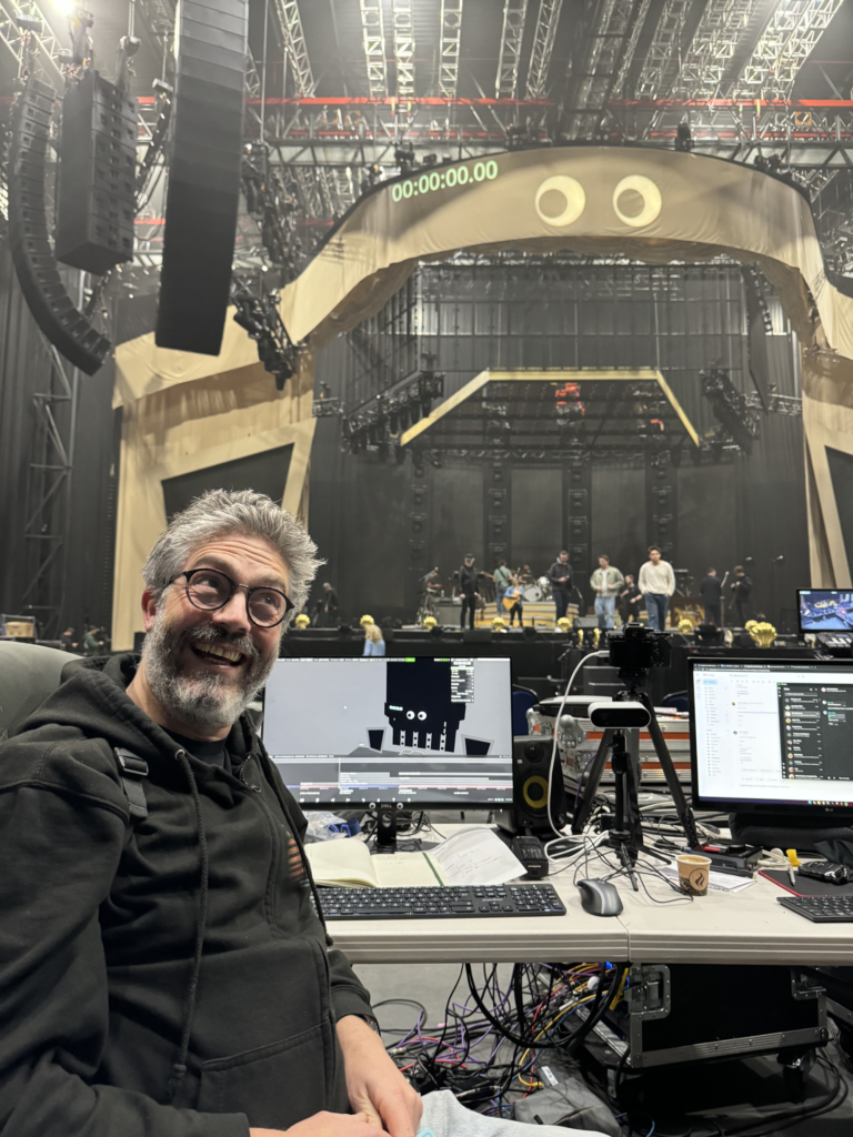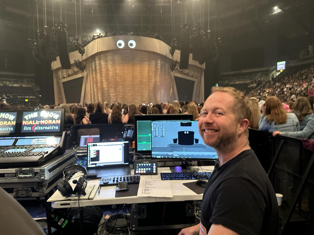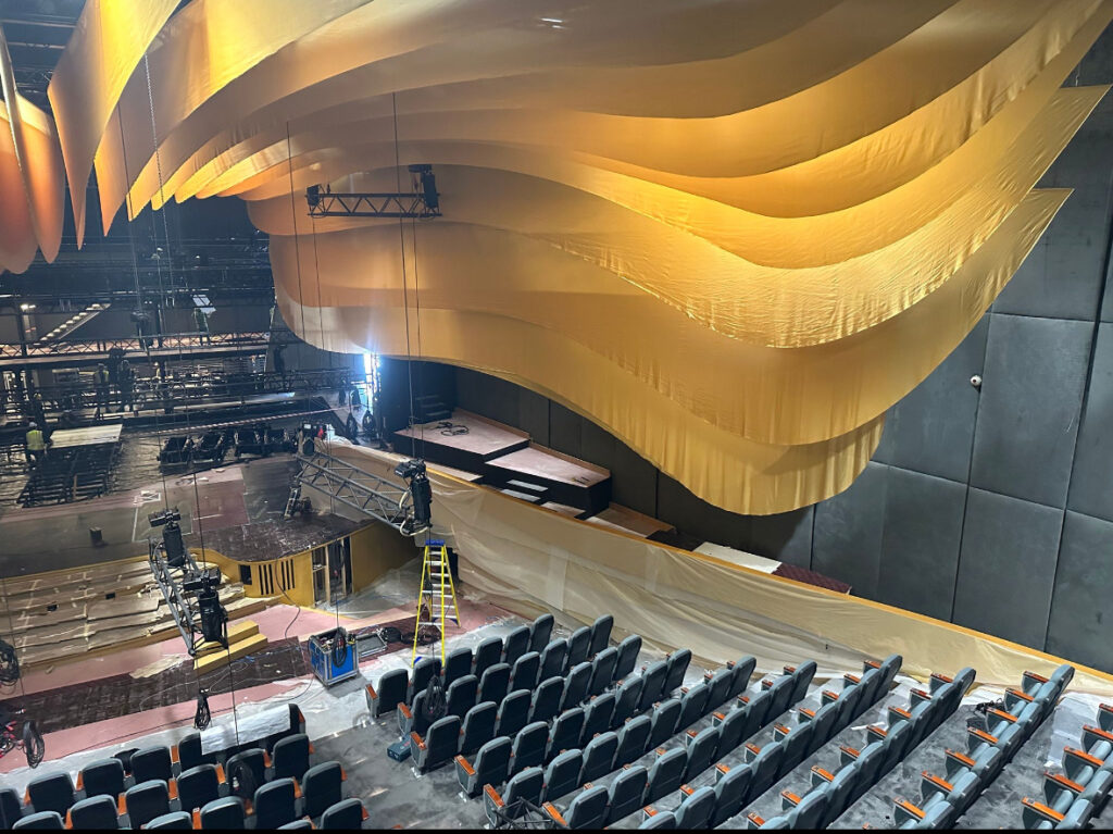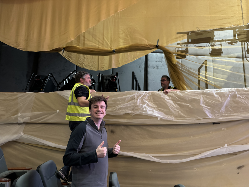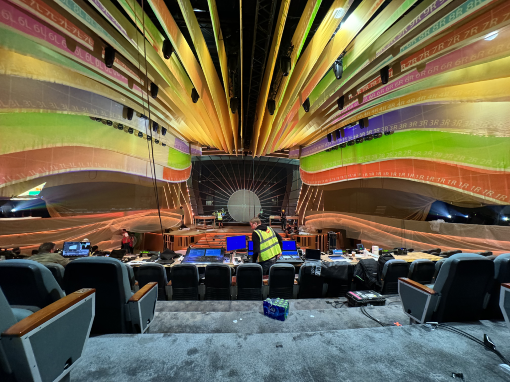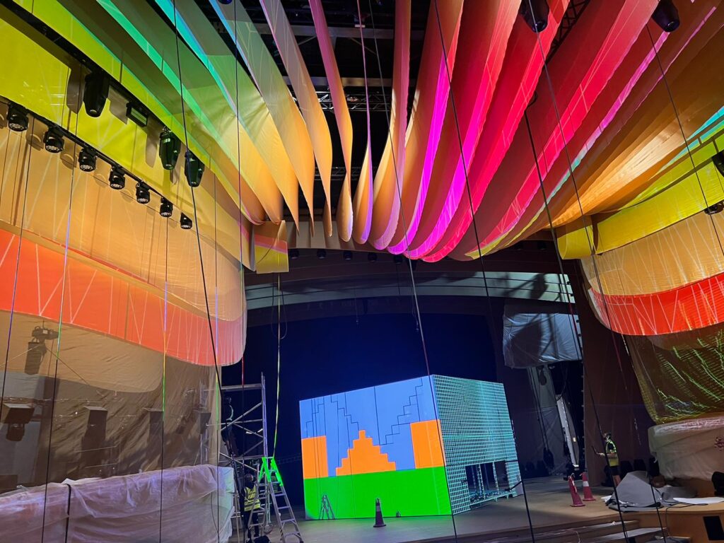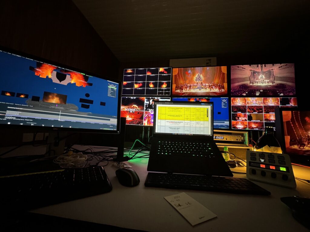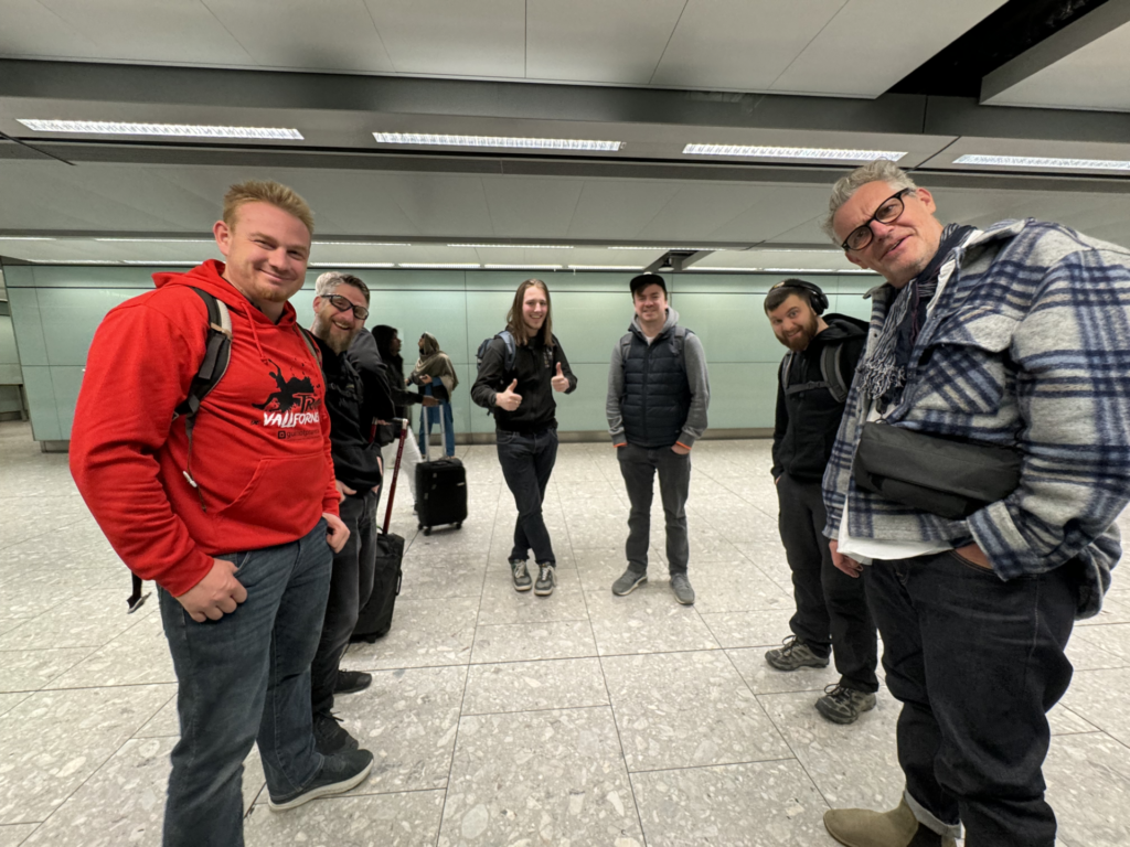
Its the end of week one in Basel on ESC2025 and I’m aiming to keep a weekly blog of the going on’s of what we have been up to as the screens department. I’m not going to be publishing this until the show is over so as not to reveal any secrets of the show. A while back I got a call of my good friend Sam to see if I was interested in joining him as part of the video screens team and when I heard who was going to be involved I checked my diary to make sure I was free and said yes!
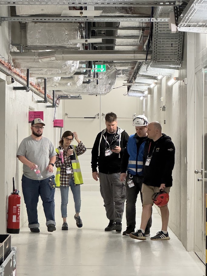
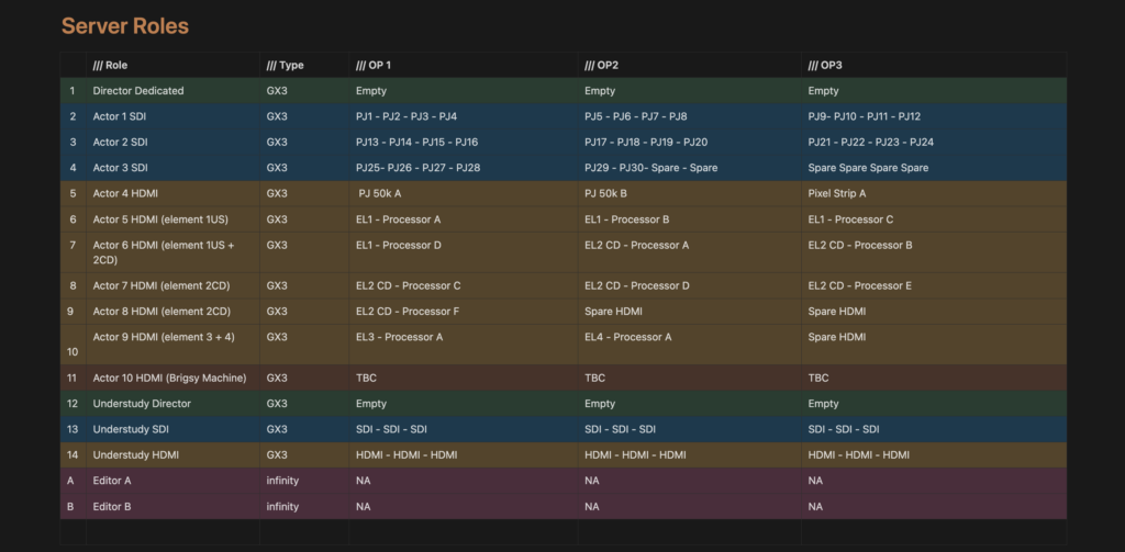
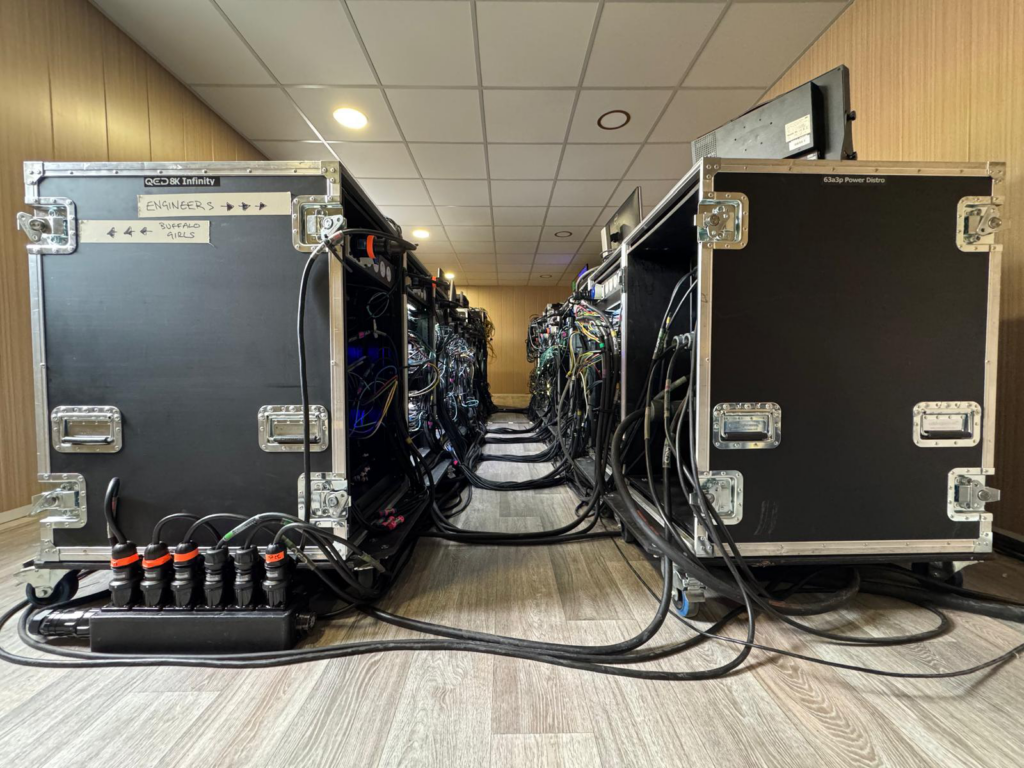
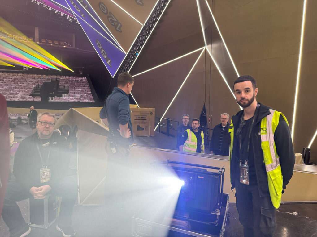
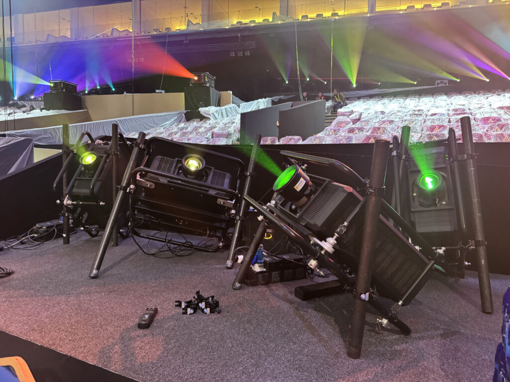
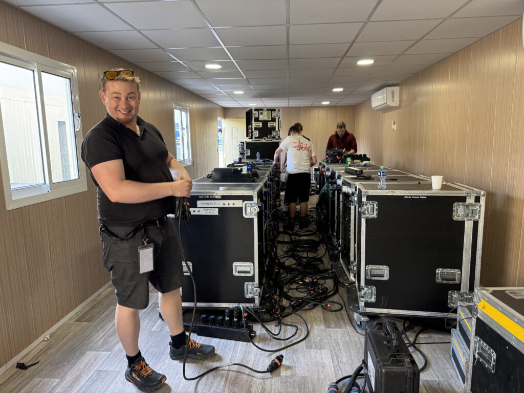
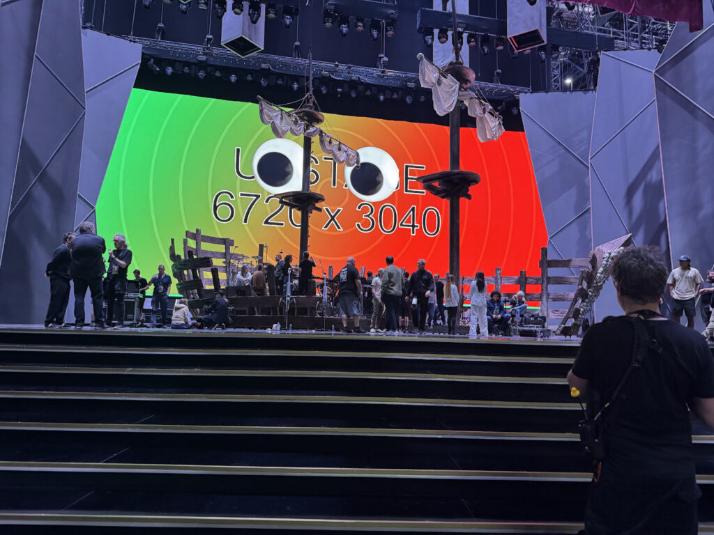
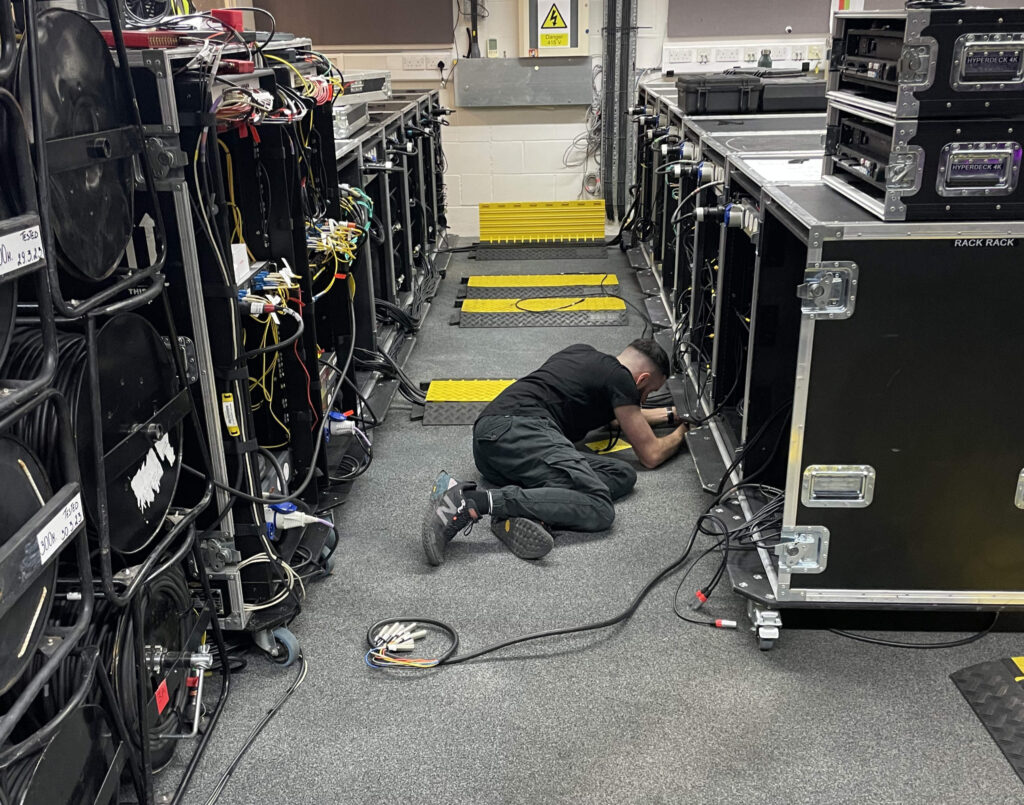
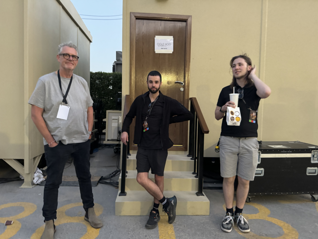
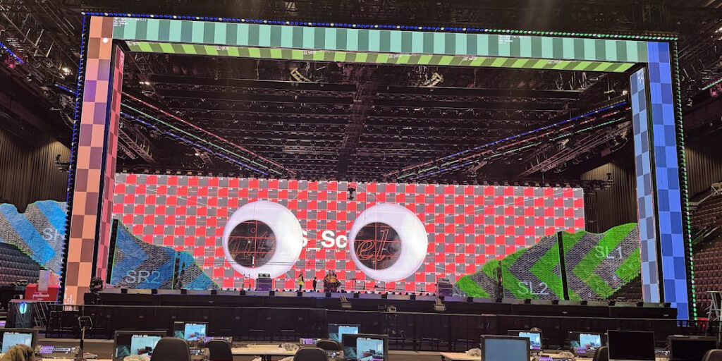
Fast forward a few month’s and I was heading to Basel to meet Sam, Luke & Emily to start our first day onsite at St. Jakobshalle and meet the team from CT Sweden who were delivering all the screen , projection and server infrastructure. Sam had been in many meetings with CT Sweden for several weeks before and specced the system so when we arrived onsite everything was ready and setup for us. The guys had done a great job of getting the system up and running to to a point where we could push our show file over and get setup to start receiving content and building a show. We had already spent a week at Neg Earth with the lighting team before coming to Basel so we already had quite a fleshy show file to hit the ground running on arrival.
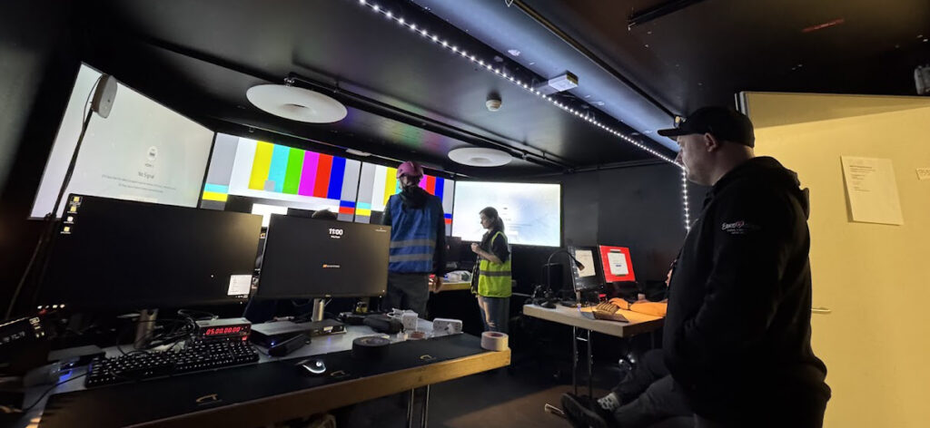
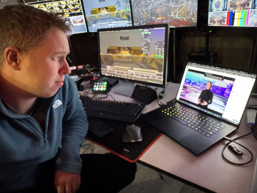
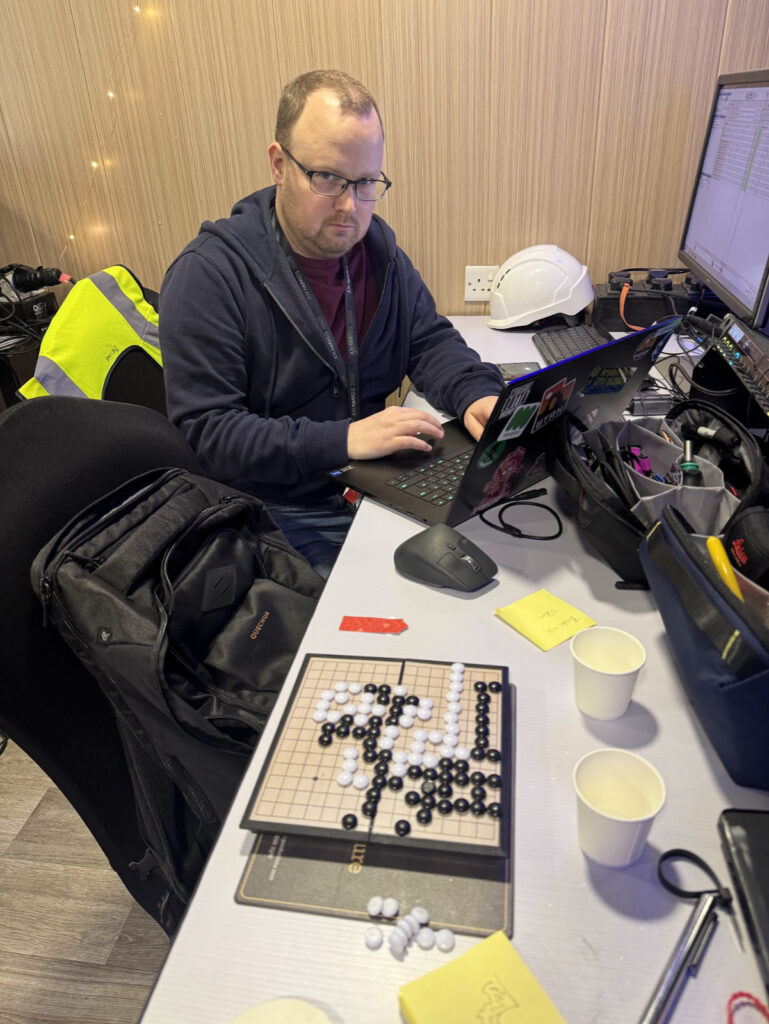
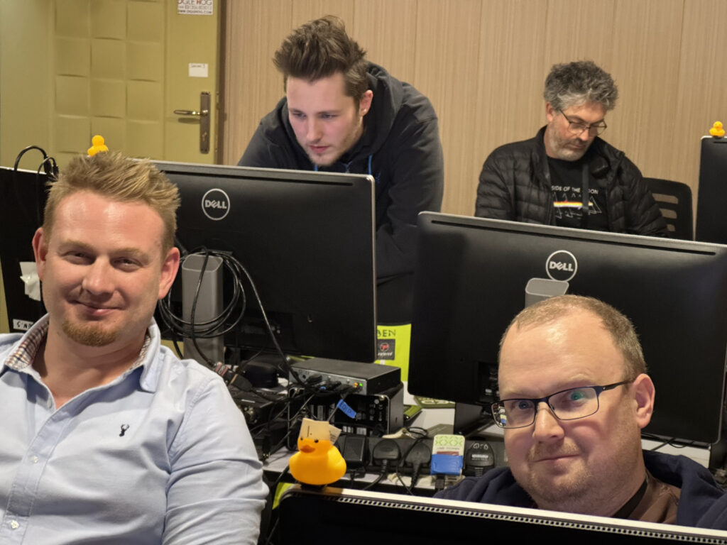
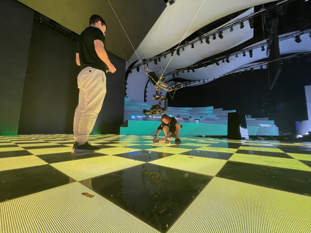
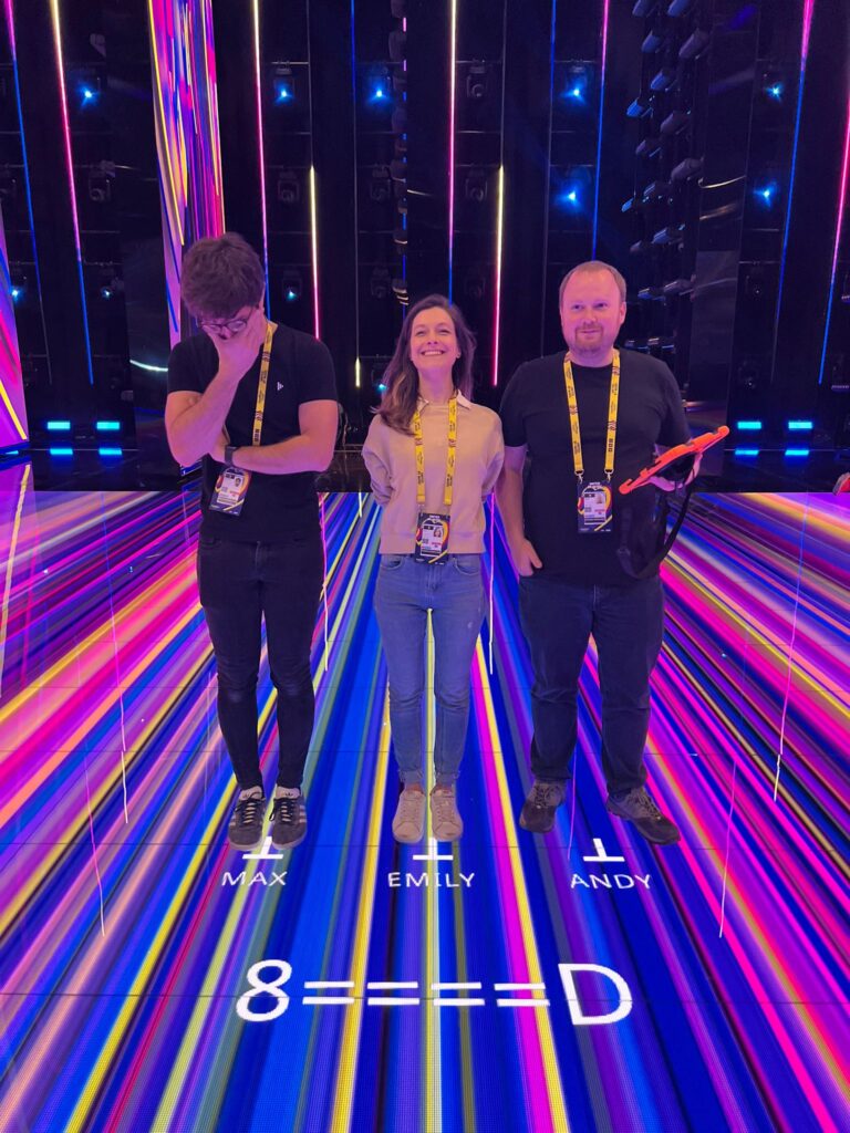
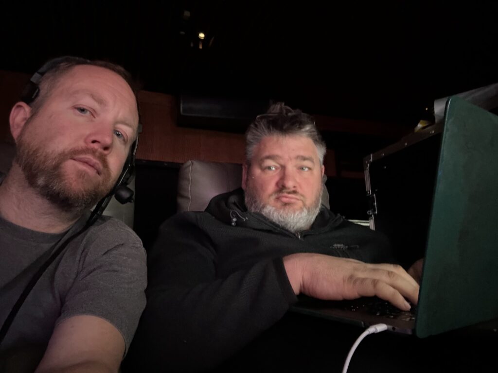
Day 1 was us getting our personal machines setup and connected into the system, getting to know our new collages and generally getting bedded in ready for a month of making a show. Luke & Emily were in charge of programming, Sam was Screens producer and client facing and I was associate screens producer supporting Sam and looking after content wrangling, technical back end things.

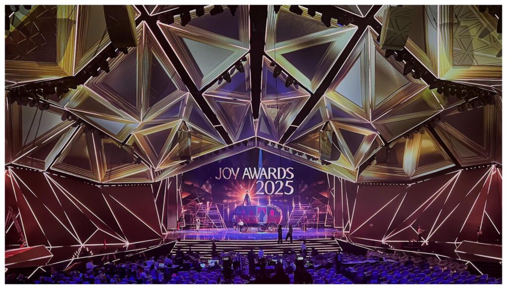
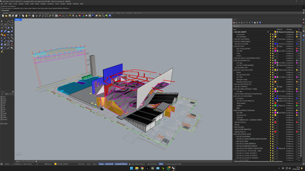
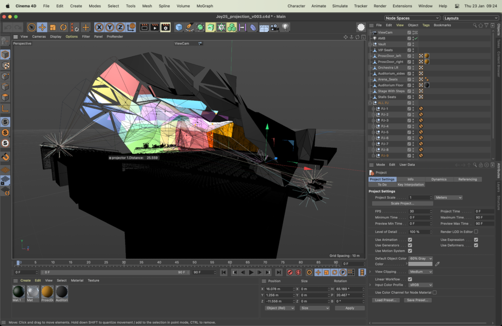
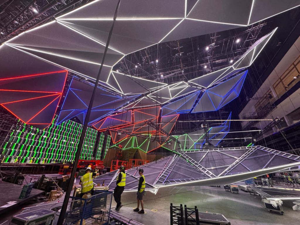
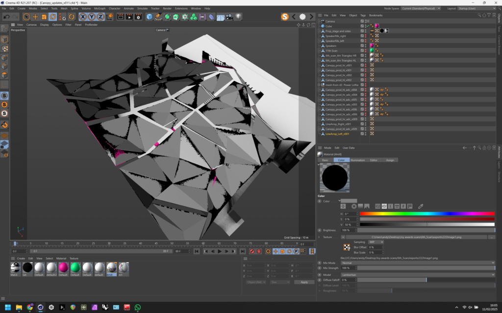
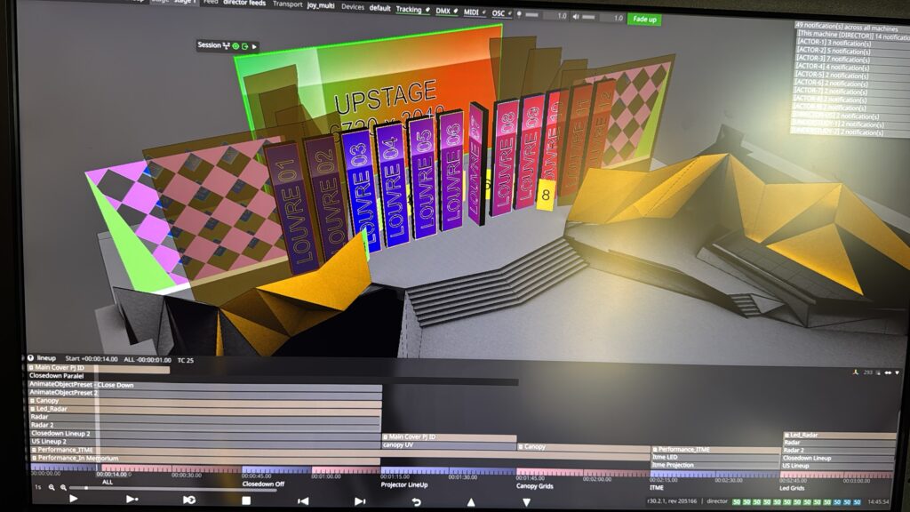
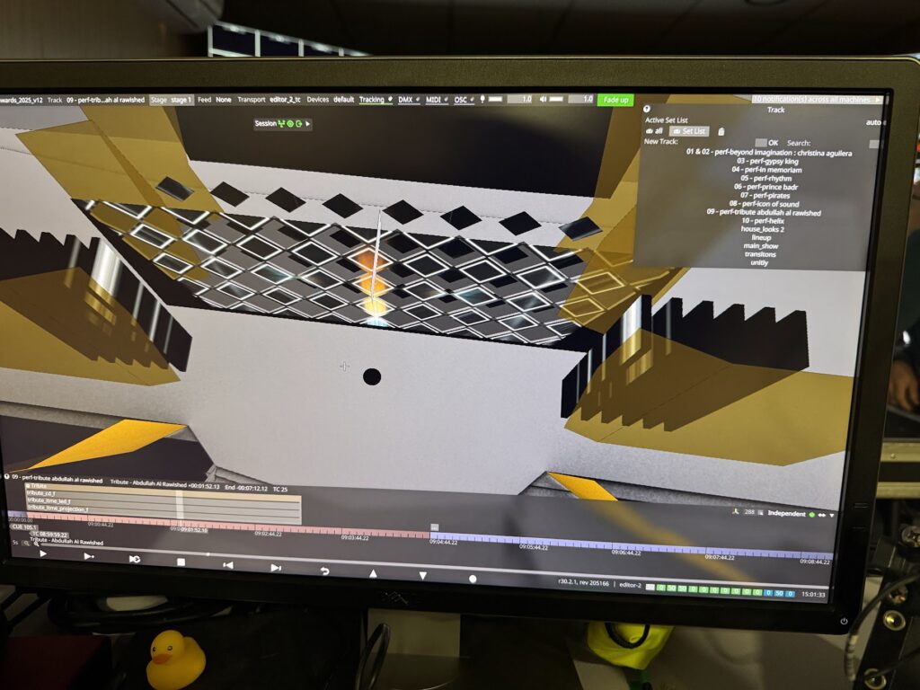
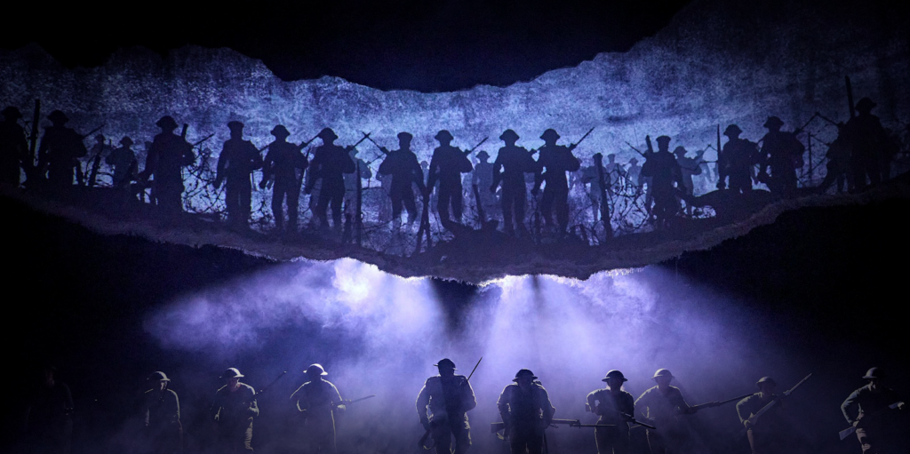
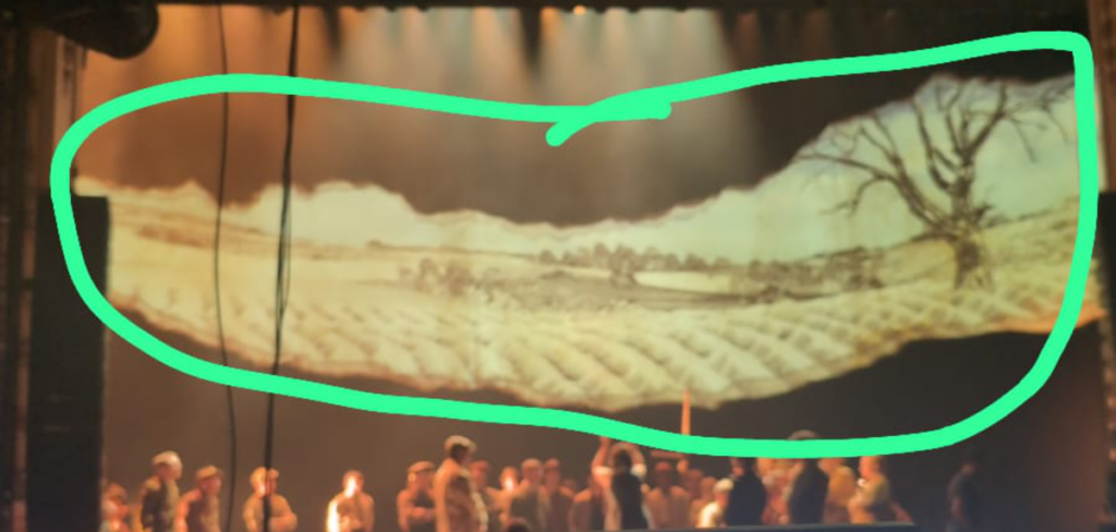
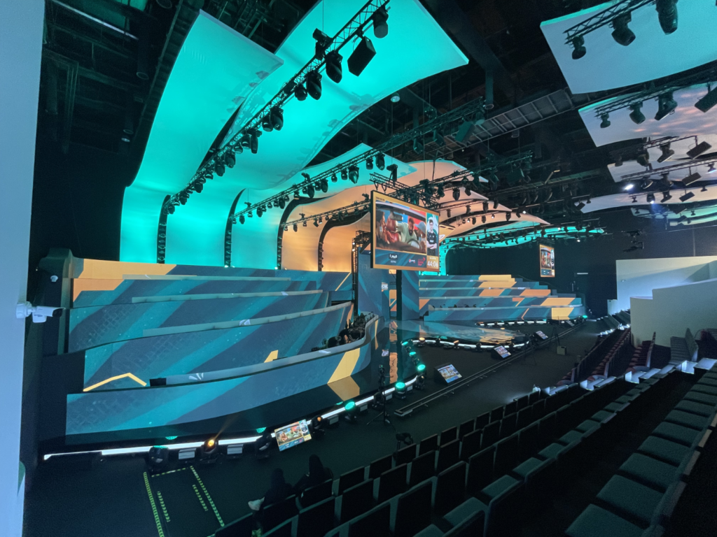
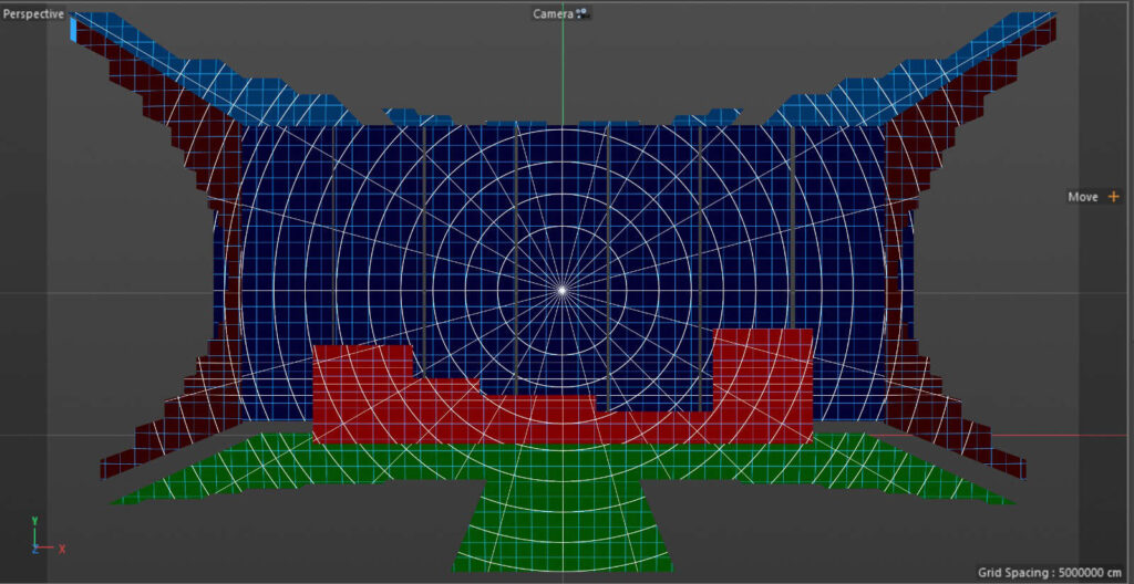
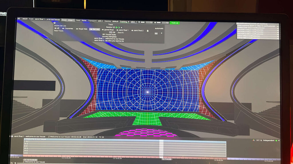
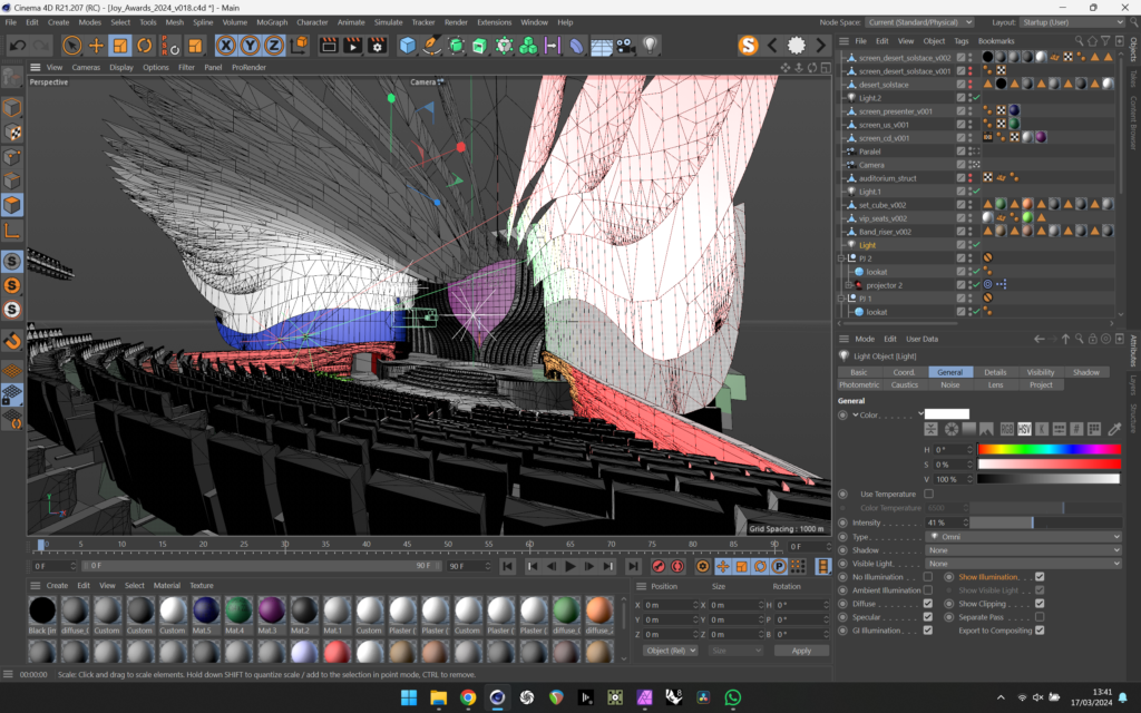
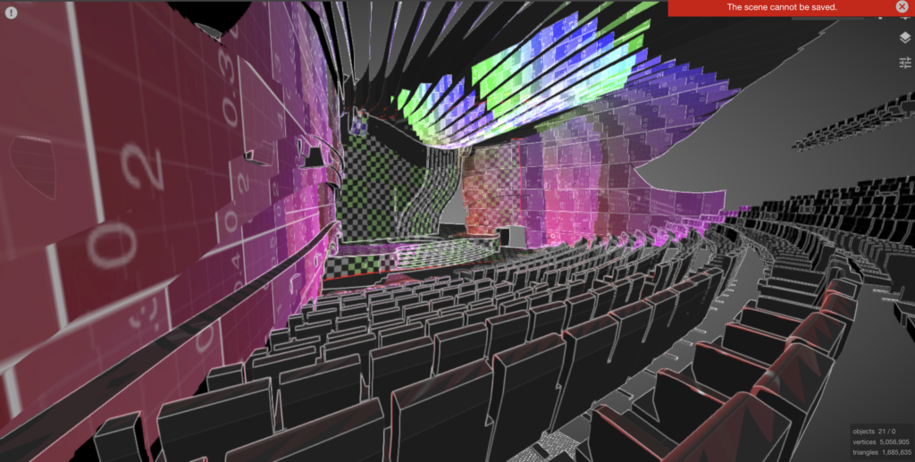
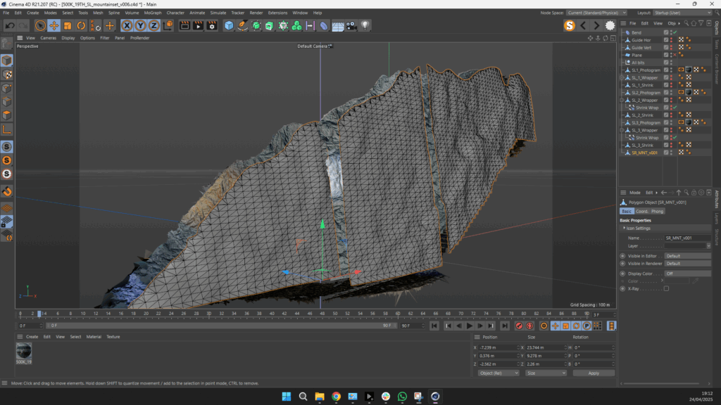
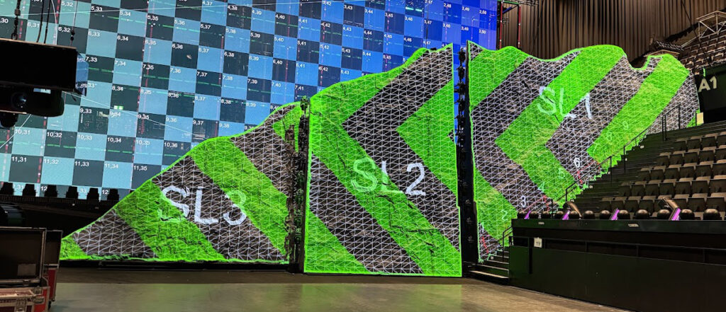
For the set design we had some sculpted mountains left and right of the stage that were to be projected on. Prior to coming to site had made a preliminary model from the CAD plans as a rough guide for the content teams but as the mountain surface was basically sculpted by hand we needed an accurate as built model.
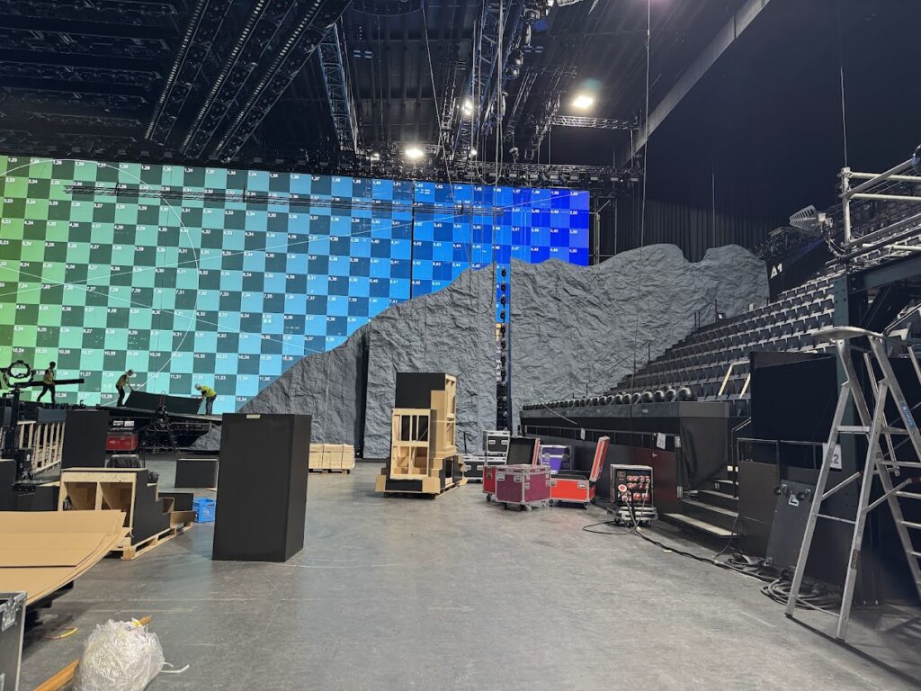
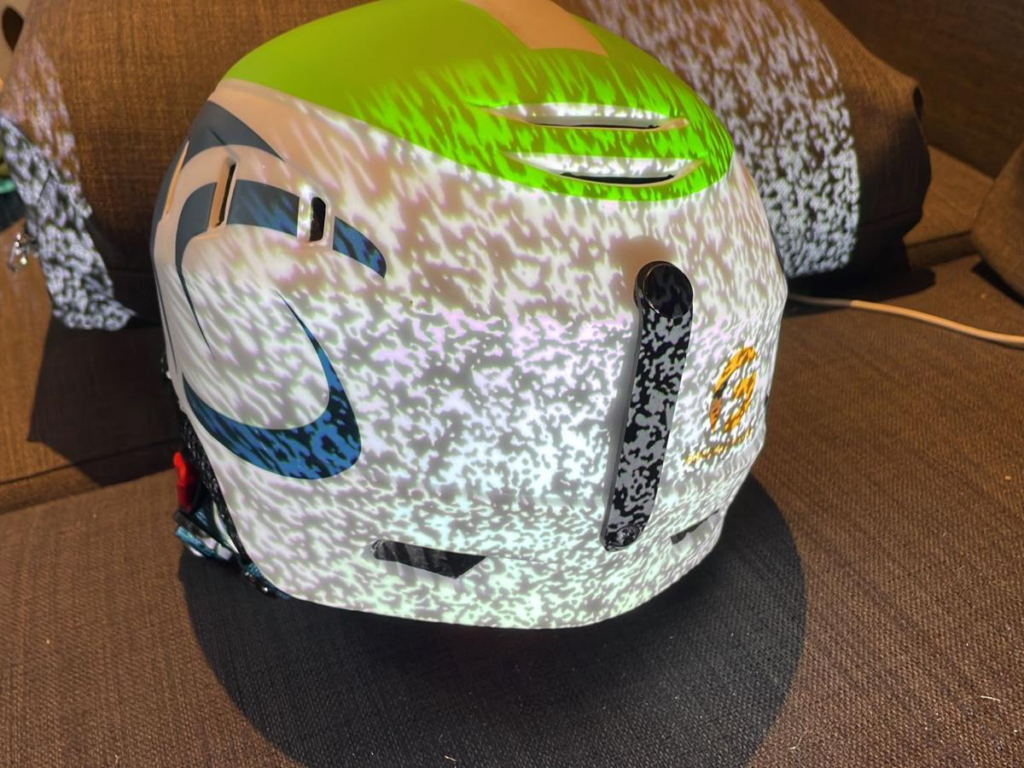
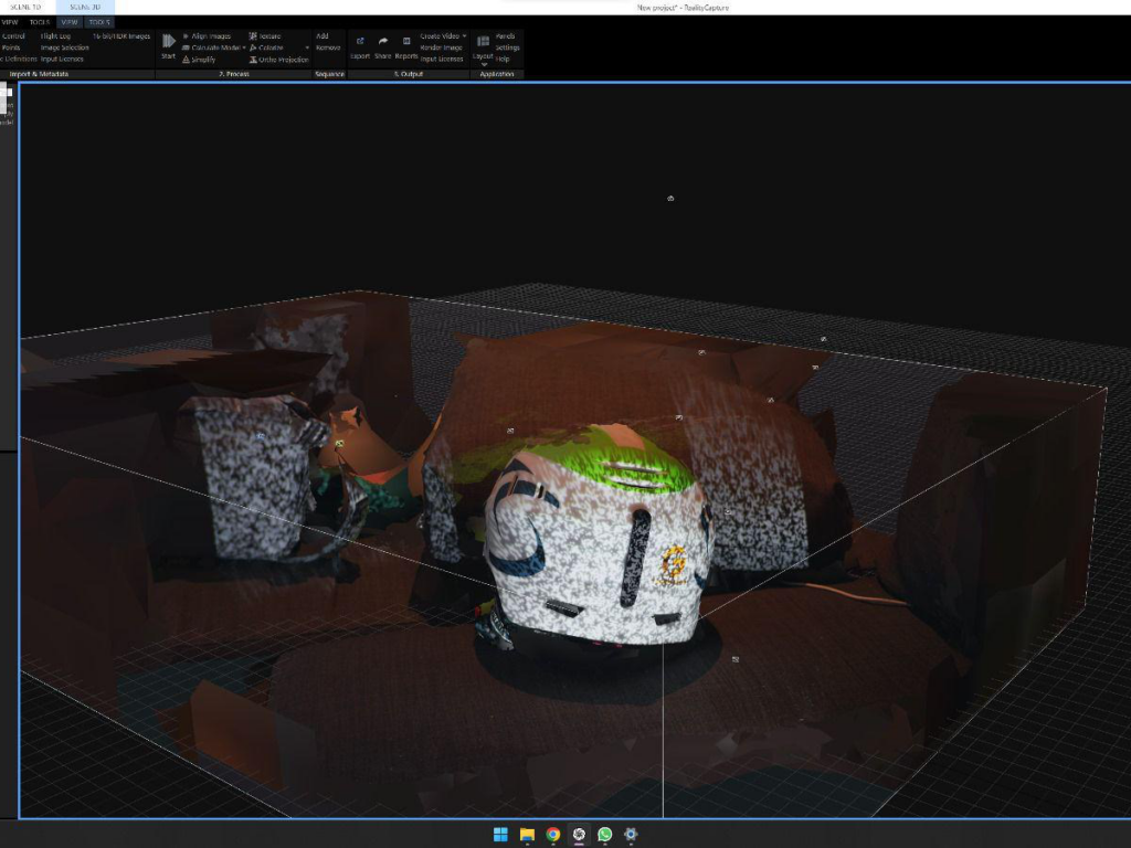
CT had brought their Leica BLK lidar scanner to scan the mountains but as I had some time and access during the day and i had brought my camera (Sony a7V) I decided to do a photogrammetry construction test which turned out so well I decided to photogram’ the whole mountain.
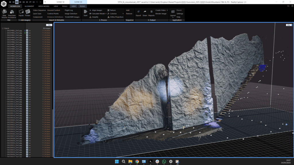
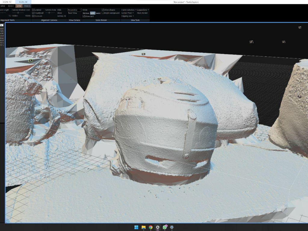
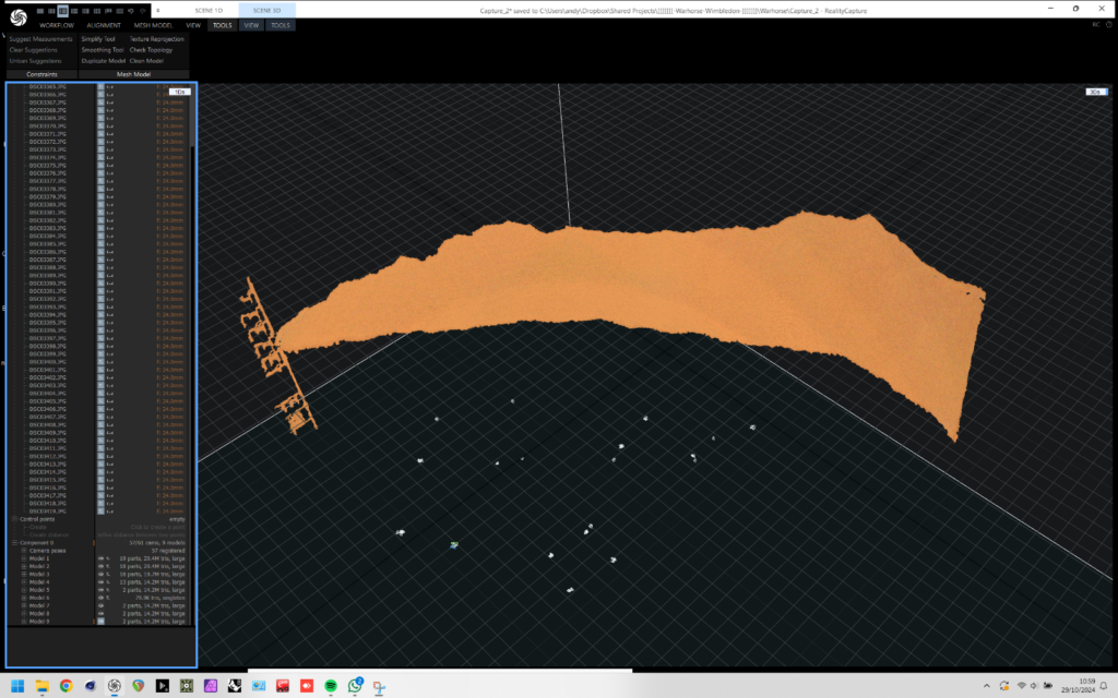
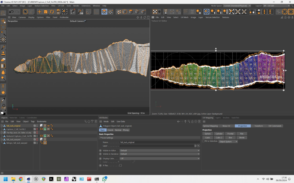
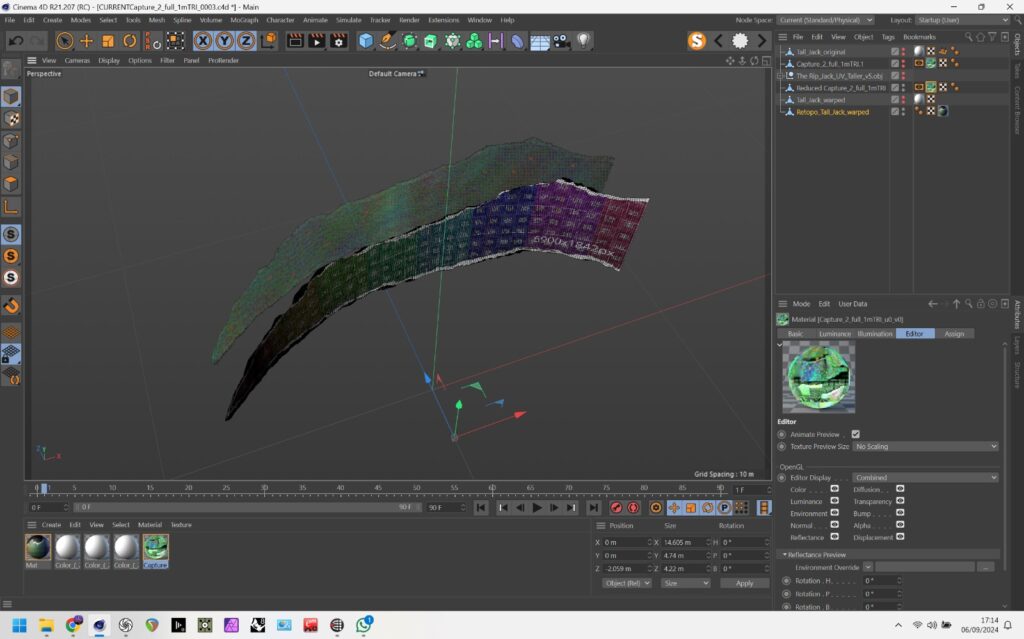
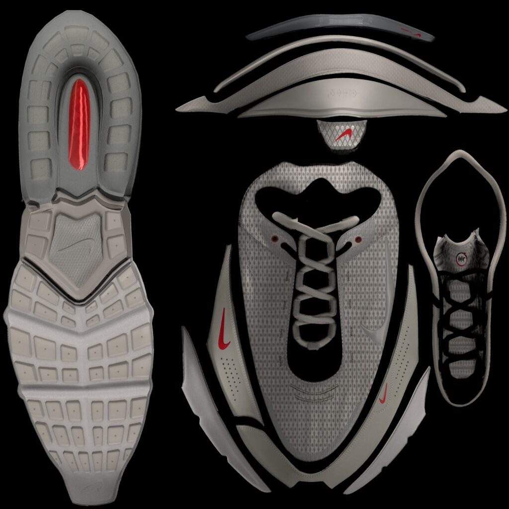
With around 90 photos and a little bit of tweaking of the RAW images in DXO I got a great construction result in Reality Capture shown in the image above. From here I simplified the model down to around 500k triangles and exported it with a texture as a FBX to bring into cinema. I’ve been working on this technique for a while for retopology where I take a clean uniform geometry, cut it out using the capture model as a guide and then shrink wrap the clean geo onto the high poly mesh. Its not a quick process and worth taking the time to get this right as this forms the foundation of s good lineup.
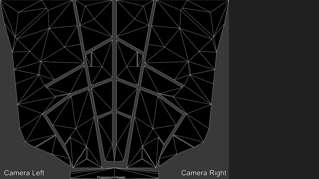
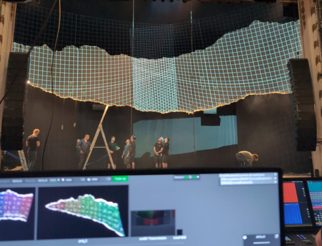
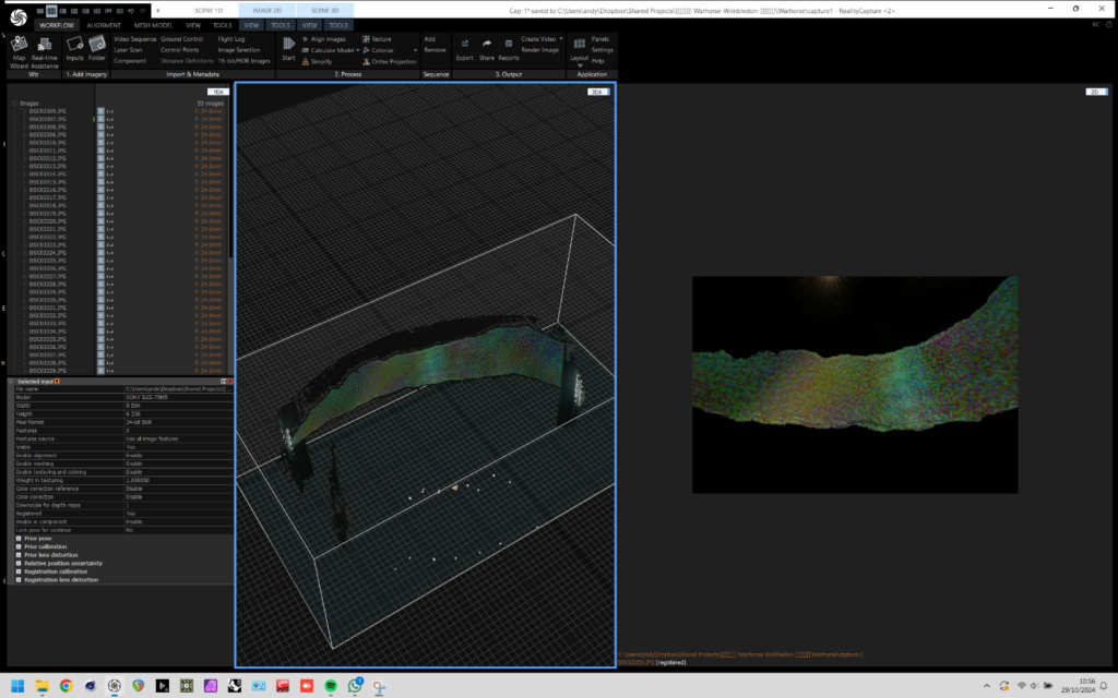
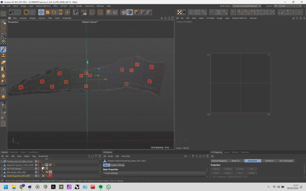
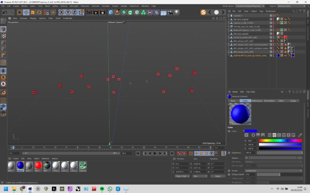
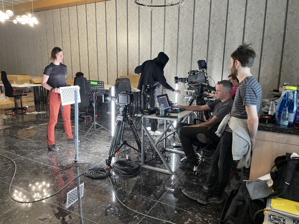
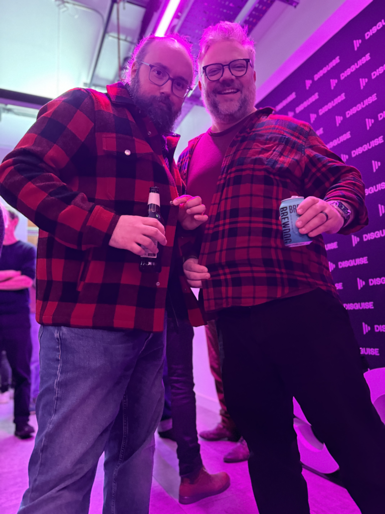
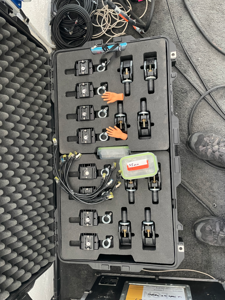
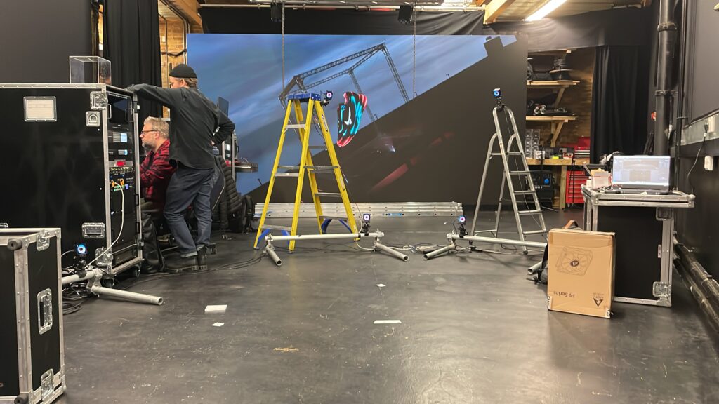
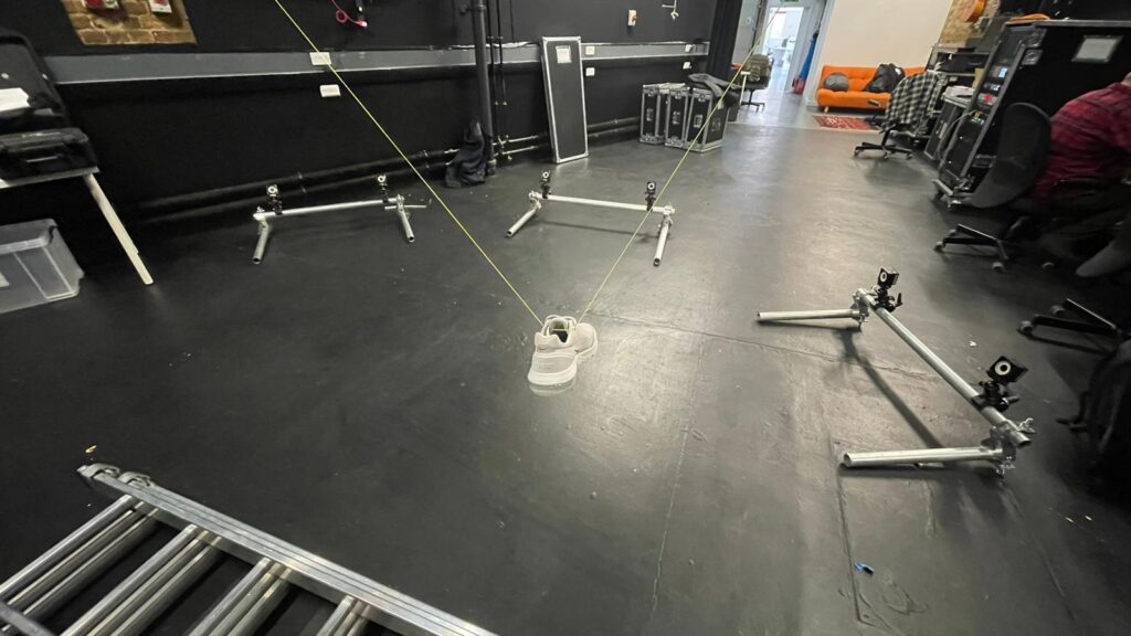
CT had spoke with disguise and they were supplying some Omnical cameras and someone to be onsite to look after this, and it was nice to see that Nicholas Defonzo was over to look after this. Once we got a clear area the cameras finally fixed solid Nicholas got a decent Omnical result
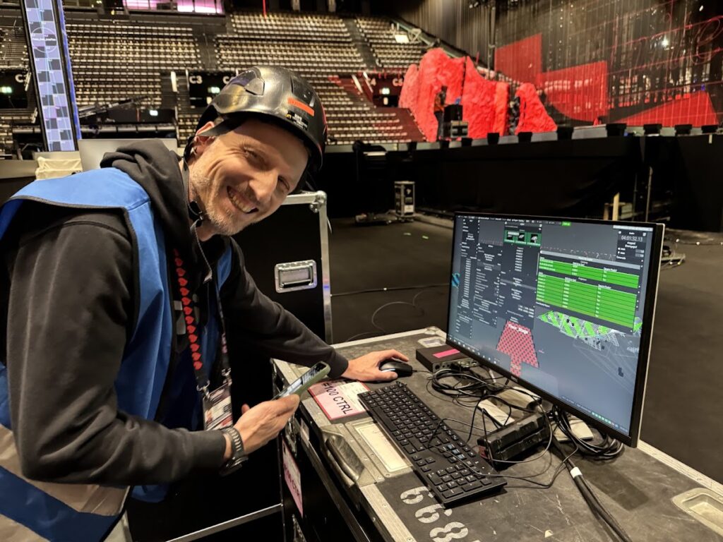
The whole thing could have been quickcal’d quite quickly but wasn’t going to step on Nicolas’s toes. I did find out that later that on emails with CT, someone at d3 had been dropping my name in endorsement using omnical unbeknown to me and I’m unhappy about it. There are several issues with using omnical on a gig like this and one of the big ones is that when a capture is in progress no-one else can use the director and work in parallel which is cumbersome and generally all the infrastructure that needs to be in place before a line-up can be achieved. I must say that when omnical does work, its really great it just takes a lot of effort to get there. I’m really happy that Nicolas was here here to look after the quirks of omnical and he’s also an all round great guy.
There’s been a huge amount of discontent with disguise for quite a while within the user community. I have no idea what’s going on with disguise but from the outside looking in it seem a bit of a mess though our interactions with them the last couple of weeks . Its been great having Joe T here as onsite support taking all of our flack and looking after bug tracking and developer communication with the delicate IPVFC cards. Were all interested to see the marketing from d3 after this to see how honest it is about their involvement.
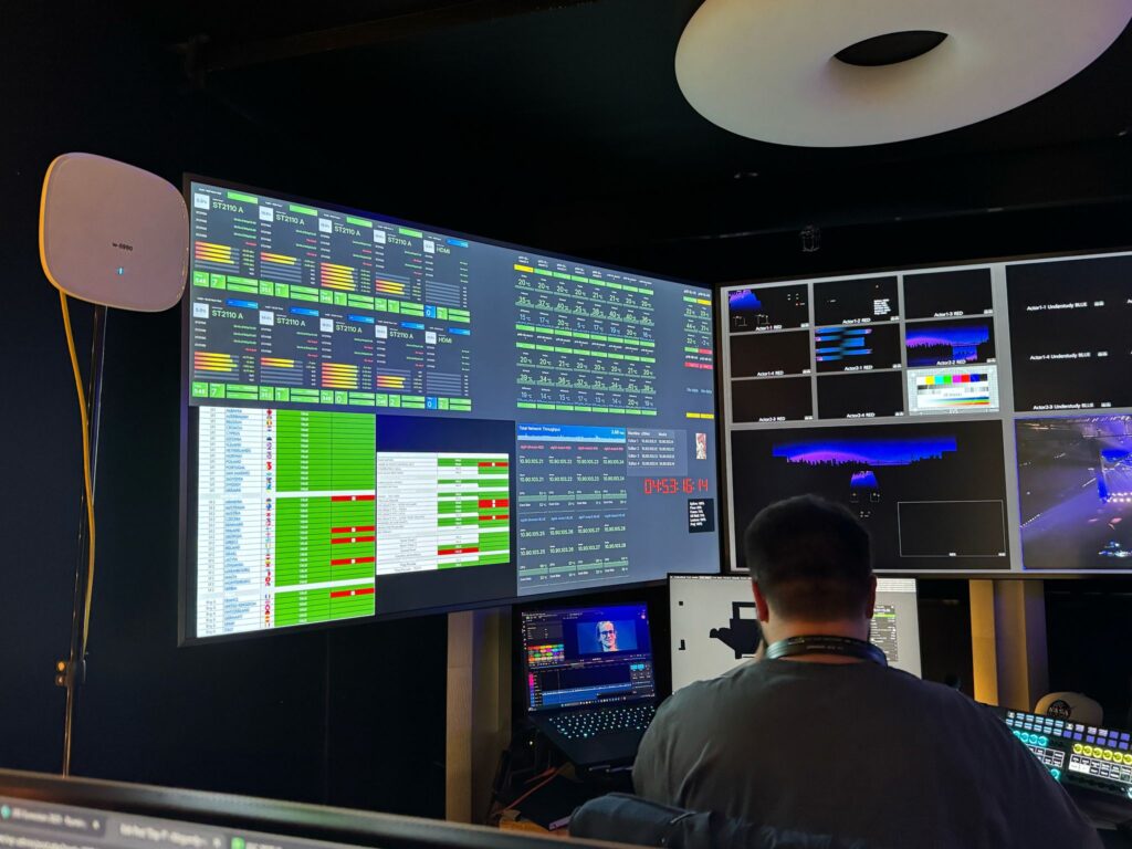
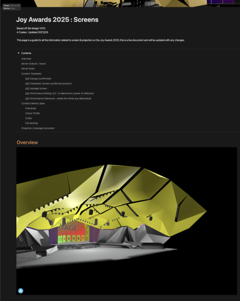
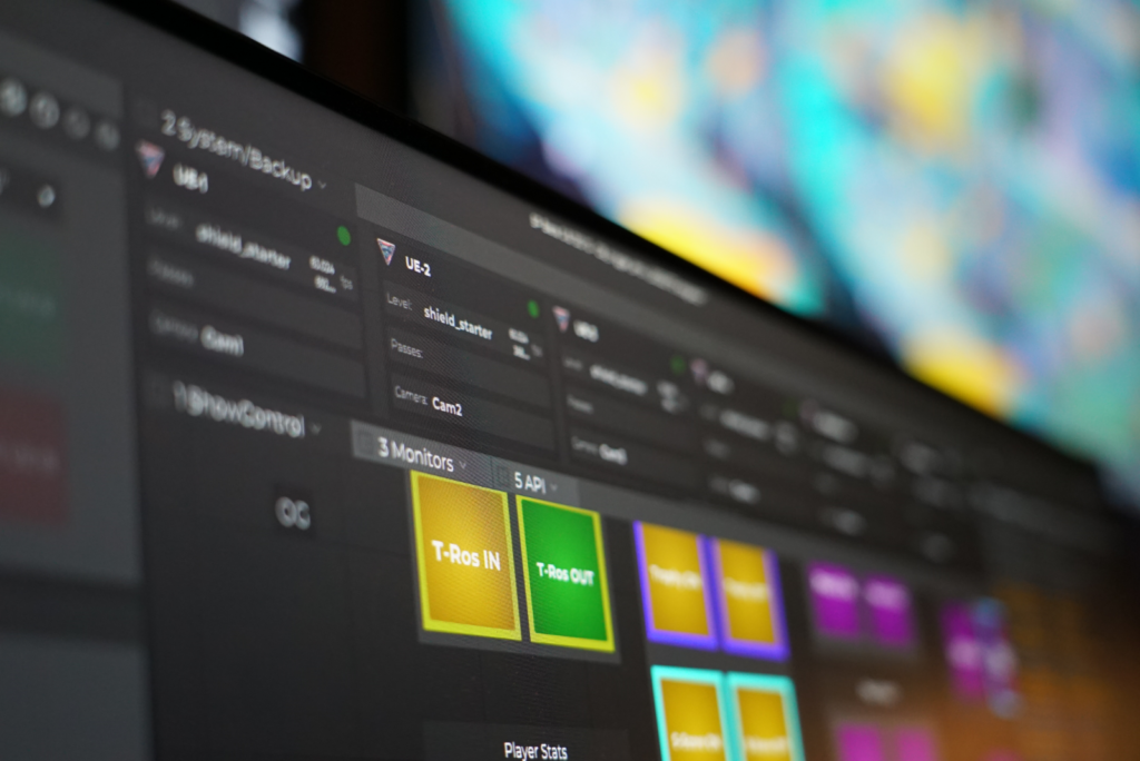
During our time in previz at Neg we put together a workflow for content ingestion and management so we were all in the loop with new delivery’s and update’s. I started a fresh google sheet a few weeks back based on when we did Eurovision at Liverpool and once we were together we collectively made improvements and implemented ideas to make a good foundation when we got onsite in Basel. Based on the multiple tabs of different deliveries Luke made a master overview sheet that highlighted red when new content was in and any version updates. Philip who was part of the CT team looking after systems built us a great dashboard page for systems and integrated the overview page of our content tracker so we all had optics on what we had and what we didn’t.
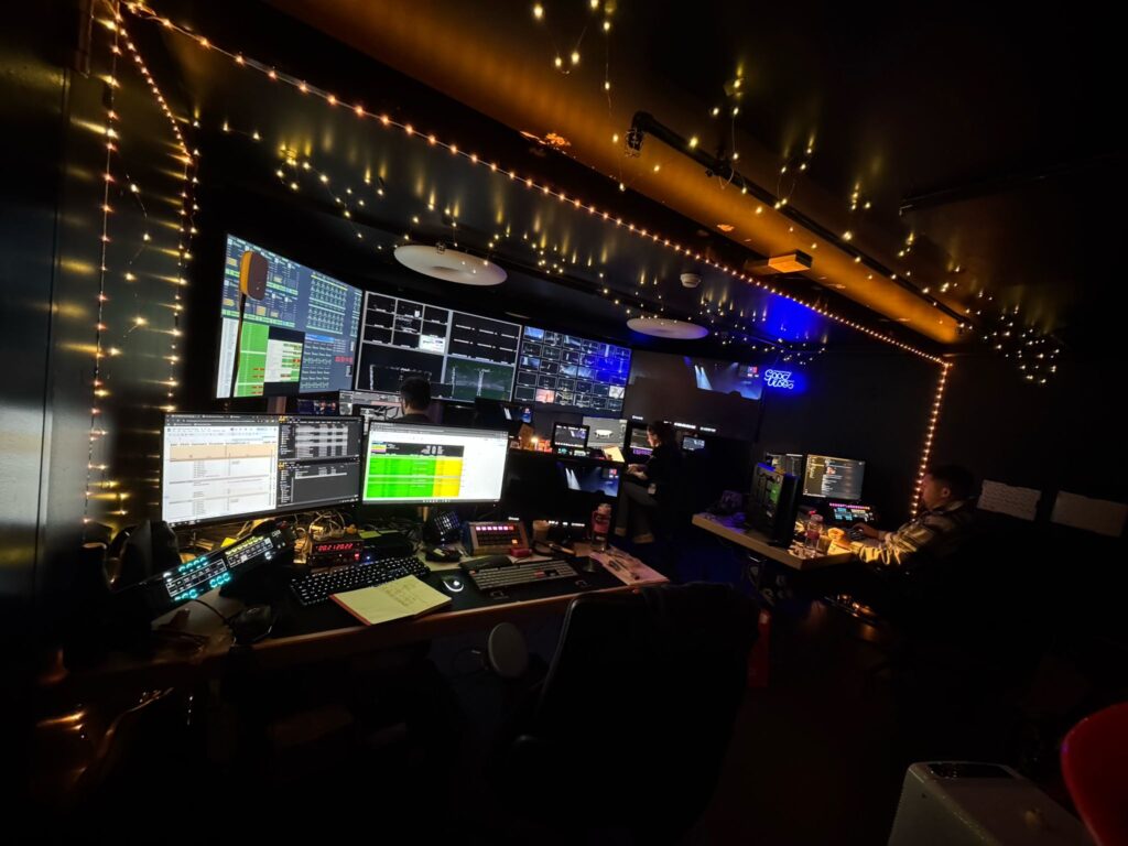
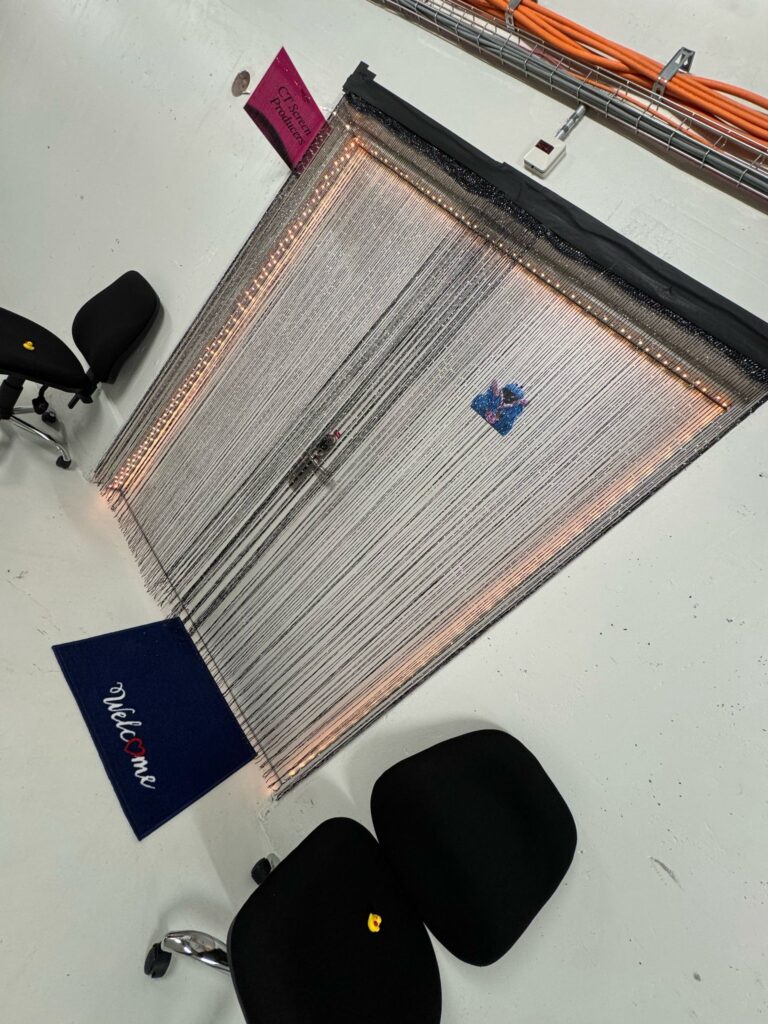
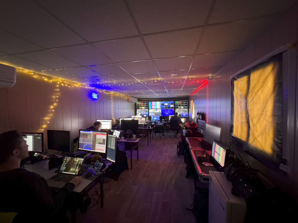
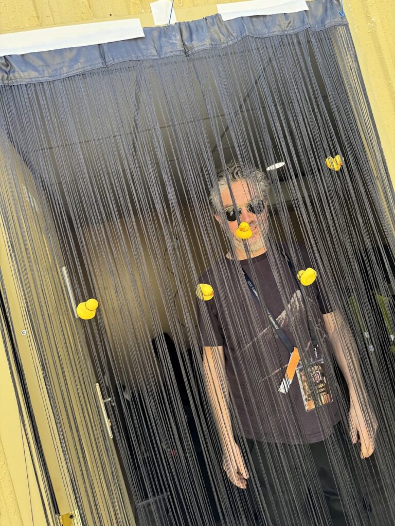
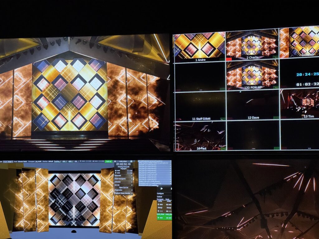
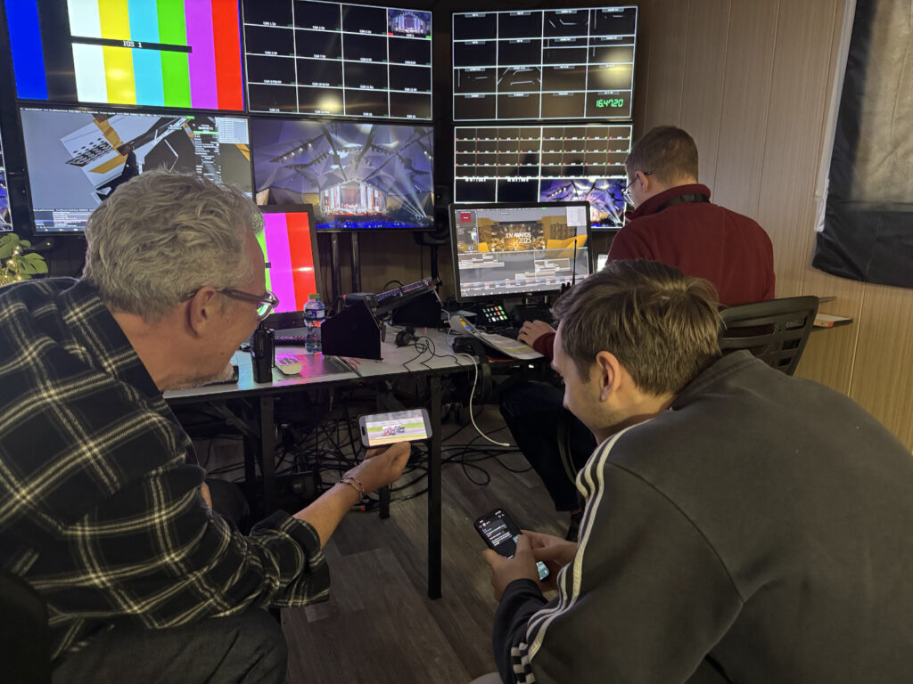
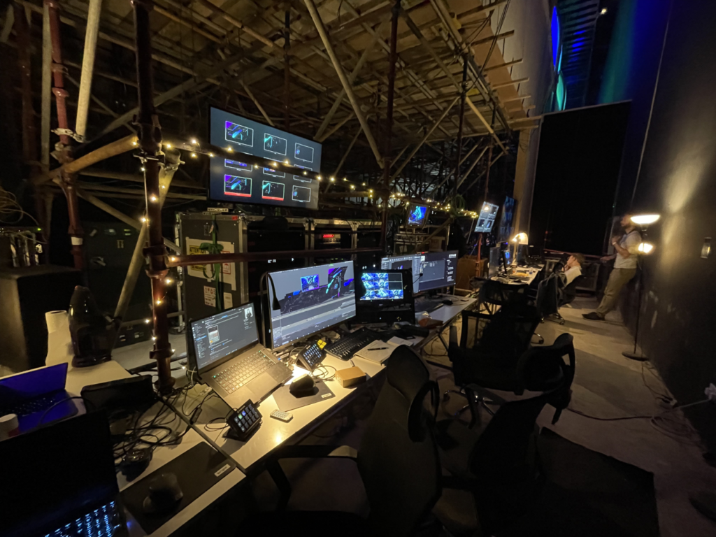
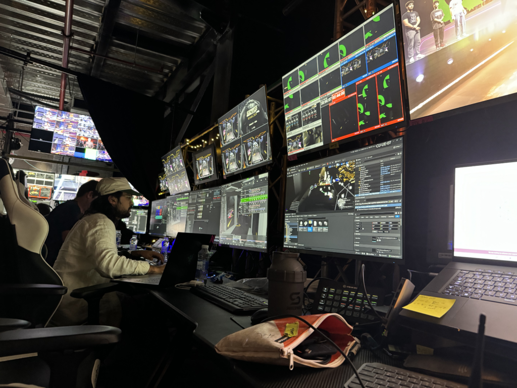
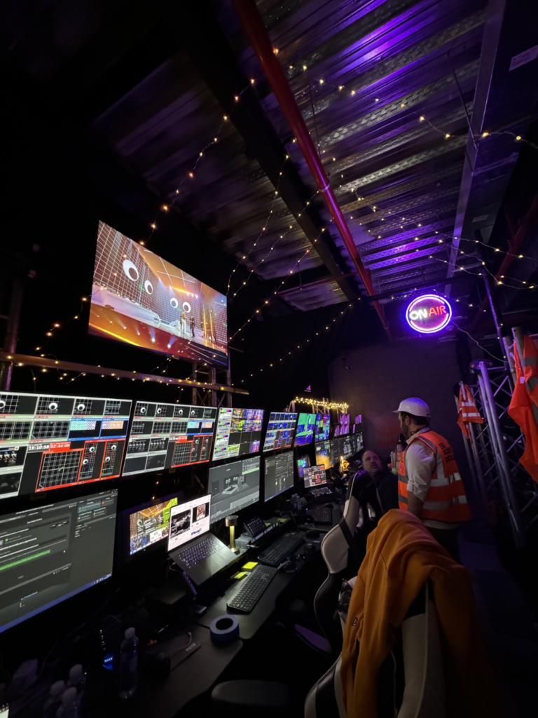
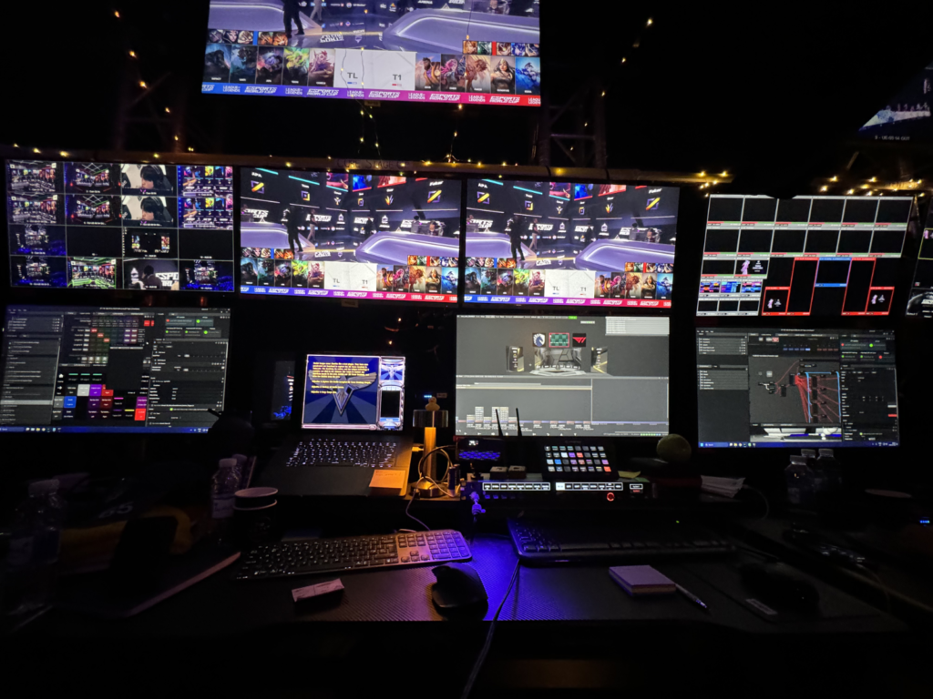
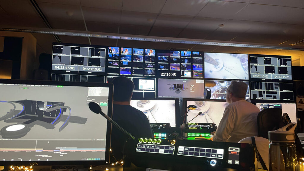
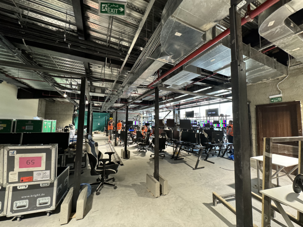
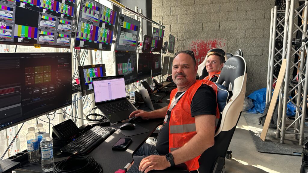
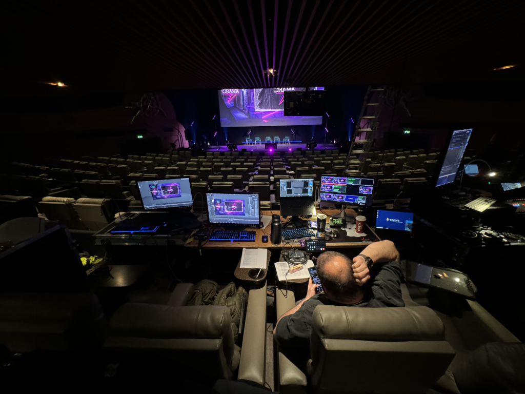
Its been a great first week with a huge amount of work from everyone, we started the first day of stand in rehearsals today with everything going smoothly. Throughout the week we have been decorating our control room with some string lights and led tape I brought with me. Today we found a Eurovision looking doormat in the Aldi over the road so we bought it and added it to the decorations, that’s it for this week!!
